
EtherNet/IP Network Devices
User Manual
Original Instructions
2 Rockwell Automation Publication ENET-UM006B-EN-P - May 2022
EtherNet/IP Network Devices User Manual
Important User Information
Read this document and the documents listed in the additional resources section about installation, configuration, and
operation of this equipment before you install, configure, operate, or maintain this product. Users are required to familiarize
themselves with installation and wiring instructions in addition to requirements of all applicable codes, laws, and standards.
Activities including installation, adjustments, putting into service, use, assembly, disassembly, and maintenance are required to
be carried out by suitably trained personnel in accordance with applicable code of practice.
If this equipment is used in a manner not specified by the manufacturer, the protection provided by the equipment may be
impaired.
In no event will Rockwell Automation, Inc. be responsible or liable for indirect or consequential damages resulting from the use
or application of this equipment.
The examples and diagrams in this manual are included solely for illustrative purposes. Because of the many variables and
requirements associated with any particular installation, Rockwell Automation, Inc. cannot assume responsibility or liability for
actual use based on the examples and diagrams.
No patent liability is assumed by Rockwell Automation, Inc. with respect to use of information, circuits, equipment, or software
described in this manual.
Reproduction of the contents of this manual, in whole or in part, without written permission of Rockwell Automation, Inc., is
prohibited.
Throughout this manual, when necessary, we use notes to make you aware of safety considerations.
Labels may also be on or inside the equipment to provide specific precautions.
WARNING: Identifies information about practices or circumstances that can cause an explosion in a hazardous environment, which
may lead to personal injury or death, property damage, or economic loss.
ATTENTION: Identifies information about practices or circumstances that can lead to personal injury or death, property
damage, or economic loss. Attentions help you identify a hazard, avoid a hazard, and recognize the consequence.
IMPORTANT Identifies information that is critical for successful application and understanding of the product.
SHOCK HAZARD: Labels may be on or inside the equipment, for example, a drive or motor, to alert people that dangerous
voltage may be present.
BURN HAZARD: Labels may be on or inside the equipment, for example, a drive or motor, to alert people that surfaces may
reach dangerous temperatures.
ARC FLASH HAZARD: Labels may be on or inside the equipment, for example, a motor control center, to alert people to potential
Arc Flash. Arc Flash will cause severe injury or death. Wear proper Personal Protective Equipment (PPE). Follow ALL Regulatory
requirements for safe work practices and for Personal Protective Equipment (PPE).

Rockwell Automation Publication ENET-UM006B-EN-P - May 2022 3
Table of Contents
Table of Contents . . . . . . . . . . . . . . . . . . . . . . . . . . . . . . . . . . . . . . . . . . . . . . . 3
Preface . . . . . . . . . . . . . . . . . . . . . . . . . . . . . . . . . . . . . . . . . . . . . . . . . . . . . . . 5
About This Publication . . . . . . . . . . . . . . . . . . . . . . . . . . . . . . . . . . . . . . . . . . . 5
Inclusive Terminology . . . . . . . . . . . . . . . . . . . . . . . . . . . . . . . . . . . . . . . . 5
Summary of Changes. . . . . . . . . . . . . . . . . . . . . . . . . . . . . . . . . . . . . . . . . . . . . 5
Additional Resources . . . . . . . . . . . . . . . . . . . . . . . . . . . . . . . . . . . . . . . . . . . . . 6
Chapter 1
EtherNet/IP Protocol Terminology . . . . . . . . . . . . . . . . . . . . . . . . . . . . . . . . . . . . . . . . . . . . . . . . 10
TCP Connections . . . . . . . . . . . . . . . . . . . . . . . . . . . . . . . . . . . . . . . . . . . . 10
CIP Connections . . . . . . . . . . . . . . . . . . . . . . . . . . . . . . . . . . . . . . . . . . . . 11
CIP Connection Message Types . . . . . . . . . . . . . . . . . . . . . . . . . . . . . . . 11
CIP Transport Types . . . . . . . . . . . . . . . . . . . . . . . . . . . . . . . . . . . . . . . . . 12
Implicit Messages . . . . . . . . . . . . . . . . . . . . . . . . . . . . . . . . . . . . . . . . . . . 13
Explicit Messages. . . . . . . . . . . . . . . . . . . . . . . . . . . . . . . . . . . . . . . . . . . . 14
Chapter 2
Ethernet Features in Network
Devices
EtherNet/IP Device-Specific Features . . . . . . . . . . . . . . . . . . . . . . . . . . . . . 16
Duplicate IP Address Detection . . . . . . . . . . . . . . . . . . . . . . . . . . . . . . . . . . 18
Duplicate IP Address Resolution . . . . . . . . . . . . . . . . . . . . . . . . . . . . . . 18
DNS Addressing . . . . . . . . . . . . . . . . . . . . . . . . . . . . . . . . . . . . . . . . . . . . . . . . 19
Socket Interface . . . . . . . . . . . . . . . . . . . . . . . . . . . . . . . . . . . . . . . . . . . . . . . . 19
Linear Network . . . . . . . . . . . . . . . . . . . . . . . . . . . . . . . . . . . . . . . . . . . . . . . . . 20
Device Level Ring . . . . . . . . . . . . . . . . . . . . . . . . . . . . . . . . . . . . . . . . . . . . . . . 21
EtherNet/IP Network Specifications . . . . . . . . . . . . . . . . . . . . . . . . . . . . . . 22
Time Synchronization . . . . . . . . . . . . . . . . . . . . . . . . . . . . . . . . . . . . . . . . . . . 23
Simple Network Management Protocol (SNMP) . . . . . . . . . . . . . . . . . . . 23
Chapter 3
Configure a Workstation to
Operate on an EtherNet/IP
Network
Configure the Ethernet Communication Driver in
FactoryTalk Linx Software . . . . . . . . . . . . . . . . . . . . . . . . . . . . . . . . . . . . . . . 26
Specify a Single IP Address or a Range of IP Addresses . . . . . . . . . . 28
Add a New Driver. . . . . . . . . . . . . . . . . . . . . . . . . . . . . . . . . . . . . . . . . . . . 29
Configure the Ethernet Communication Driver in
RSLinx Classic Software . . . . . . . . . . . . . . . . . . . . . . . . . . . . . . . . . . . . . . . . . 30

4 Rockwell Automation Publication ENET-UM006B-EN-P - May 2022
Chapter 4
Set an IP Address Set the IP Address with the EtherNet/IP Address
Commissioning Tool . . . . . . . . . . . . . . . . . . . . . . . . . . . . . . . . . . . . . . . . . . . . 33
Set Up the Tool . . . . . . . . . . . . . . . . . . . . . . . . . . . . . . . . . . . . . . . . . . . . . . 34
Assign IP Addresses Manually . . . . . . . . . . . . . . . . . . . . . . . . . . . . . . . . 35
Set the IP Address with FactoryTalk Linx Software . . . . . . . . . . . . . . . . . 39
Set the IP Address with Studio 5000 Logix Designer Application. . . . . 40
Set the IP Address with RSLinx Classic Software . . . . . . . . . . . . . . . . . . . 41
Configure Port Settings with RSLinx Classic Software . . . . . . . . . . 43
Set the IP Address with the BOOTP/DHCP Tool . . . . . . . . . . . . . . . . . . . . 44
Disable BOOTP/DHCP with RSLinx Classic Software . . . . . . . . . . . 46
DHCP Considerations . . . . . . . . . . . . . . . . . . . . . . . . . . . . . . . . . . . . . . . 48
Set the IP Address with Hardware Switches . . . . . . . . . . . . . . . . . . . . . . . 48
Reset the IP Address to Factory Default Value. . . . . . . . . . . . . . . . . . . . . . 48
Chapter 5
Configure the Device Add the Device to the Controller Organizer . . . . . . . . . . . . . . . . . . . . . . . . 49
Configure EtherNet/IP Communication . . . . . . . . . . . . . . . . . . . . . . . . . . 50
Produced and Consumed Data . . . . . . . . . . . . . . . . . . . . . . . . . . . . . . . . . . . 51
Message Instructions. . . . . . . . . . . . . . . . . . . . . . . . . . . . . . . . . . . . . . . . . . . . 51
Chapter 6
Send Email EtherNet/IP Communication Module as an Email Client. . . . . . . . . . . . 53
Send Email Via a Controller-initiated Message Instruction. . . . . . . . . . 54
Create String Tags . . . . . . . . . . . . . . . . . . . . . . . . . . . . . . . . . . . . . . . . . . 55
Enter the Ladder Logic . . . . . . . . . . . . . . . . . . . . . . . . . . . . . . . . . . . . . . . 56
Configure the MSG Instruction That Identifies the
Mail Relay Server . . . . . . . . . . . . . . . . . . . . . . . . . . . . . . . . . . . . . . . . . . . . 57
Configure the MSG Instruction That Contains the Email Text . . . 58
Configure the Email Object . . . . . . . . . . . . . . . . . . . . . . . . . . . . . . . . . . . 59
Possible Email Status Codes. . . . . . . . . . . . . . . . . . . . . . . . . . . . . . . . . . . . . . 63
Index . . . . . . . . . . . . . . . . . . . . . . . . . . . . . . . . . . . . . . . . . . . . . . . . . . . . . . . . 65

Rockwell Automation Publication ENET-UM006B-EN-P - May 2022 5
Preface
About This Publication
This manual describes how to use EtherNet/IP™ network devices in control
systems.
Make sure that you are familiar with the following:
• Use of an EtherNet/IP network
• Use of various software applications from Rockwell Automation
Inclusive Terminology
Rockwell Automation recognizes that some of the terms that are currently
used in our industry and in this publication are not in alignment with the
movement toward inclusive language in technology.
We are proactively collaborating with industry peers to find alternatives to
such terms and making changes to our products and content. Please excuse
the use of such terms in our content while we implement these changes.
Summary of Changes
This publication contains the following new or updated information. This list
includes substantive updates only and is not intended to reflect all changes.
Topic Page
EtherNet/IP Protocol 7
EtherNet/IP Network Specifications 22
Configuration Software Descriptions 25
Configure the Ethernet Communication Driver in FactoryTalk Linx Software 26
Set the IP Address with the EtherNet/IP Address Commissioning Tool 33
Set the IP Address with FactoryTalk Linx Software 39
Send Email Via a Controller-initiated Message Instruction 54
Diagnostic Webpages 65

6 Rockwell Automation Publication ENET-UM006B-EN-P - May 2022
Additional Resources
These documents contain additional information concerning related products
from Rockwell Automation.
You can view or download publications at rok.auto/literature
.
Resource Description
EtherNet/IP Media Planning and Installation Manual
Describes how to use the required media components and how to plan for, install, verify,
troubleshoot, and certify your EtherNet/IP network.
This manual is available from ODVA at: http://www.odva.org.
Ethernet/IP QuickConnect Application Technique, publication ENET-AT001
Describes EtherNet/IP QuickConnect technology and how to quickly power up and join an
EtherNet/IP network.
EtherNet/IP Socket Interface Application Technique, publication ENET-AT002
Describes the socket interface that you can use to program MSG instructions to communicate
between a Logix 5000™ controller and Ethernet devices. In this case, the interface is used
because the Ethernet devices that do not support the EtherNet/IP application protocol. Such
devices include barcode scanners, RFID readers, or other standard Ethernet devices.
Troubleshoot EtherNet/IP Networks, publication ENET-ATOO3
Describes troubleshooting techniques for Integrated Architecture® products on EtherNet/IP
networks.
EtherNet/IP Parallel Redundancy Protocol Application Technique,
publication ENET-AT006
Describes how you can configure a Parallel Redundancy Protocol (PRP) network with the 1756-
EN2TP EtherNet/IP communication module and a Stratix® 5400 or 5410 switch.
EtherNet/IP Device Level Ring, publication ENET-AT007
Describes DLR network operation, topologies, configuration considerations, and diagnostic
methods
System Security Design Guidelines Reference Manual, SECURE-RM001
Provides guidance on how to conduct security assessments, implement Rockwell Automation
products in a secure system, harden the control system, manage user access, and dispose of
equipment.
Ethernet Reference Manual, ENET-RM002
Describes basic Ethernet concepts, infrastructure components, and infrastructure features.
Industrial Components Preventive Maintenance, Enclosures, and Contact Ratings
Specifications, publication IC-TD002
Provides a quick reference tool for Allen-Bradley® industrial automation controls and
assemblies.
Safety Guidelines for the Application, Installation, and Maintenance of Solid-state
Control, publication SGI-1.1
Designed to harmonize with NEMA Standards Publication No. ICS 1.1-1987 and provides general
guidelines for the application, installation, and maintenance of solid-state control in the form of
individual devices or packaged assemblies incorporating solid-state components.
Industrial Automation Wiring and Grounding Guidelines, publication 1770-4.1
Provides general guidelines for installing a Rockwell Automation industrial system.
Product Certifications website, rok.auto/certifications
. Provides declarations of conformity, certificates, and other certification details.
Rockwell Automation Publication ENET-UM006B-EN-P - May 2022 7
Chapter 1
EtherNet/IP Protocol
EtherNet/IP™ protocol is a multi-discipline, control, and information platform
for industrial environments and time-critical applications. EtherNet/IP uses
standard Ethernet and TCP/IP technologies and an open, application-layer
protocol called the Common Industrial Protocol (CIP).
The EtherNet/IP protocol follows these standards:
• IEEE 802.3—Standard Ethernet, Precision Time Protocol (IEEE-1588)
• IETF—Internet Engineering Task Force, standard Internet Protocol (IP)
• IEC—International Electrotechnical Commission
• CIP - Common Industrial Protocol (CIP)
Application
Presentation
Session
Transport
Network
Link
Physical
CIP
Control and Information
Protocol
Ethernet
MAC
Ethernet
Physical
UDP TCP
IP
IP-Multicast
EN50170
Control International
and
IF C 61158 Standard
Request for Comments
IETF
UDP/TCP/IP
IEEE 802.3
OPEN

8 Rockwell Automation Publication ENET-UM006B-EN-P - May 2022
Chapter 1 EtherNet/IP Protocol
Common Industrial Protocol
(CIP)
CIP™ is a messaging protocol for devices in industrial automation control
systems. CIP is the application layer for the EtherNet/IP network. This
protocol implements a relative path to send a message from the producing
modules in a system to the consuming modules.
CIP uses the Producer/Consumer networking model instead of a source/
destination (Primary/Secondary) model. The Producer/Consumer model
reduces network traffic and increases speed of transmission.
In traditional I/O systems, controllers poll input modules to obtain their input
status. In the CIP system, digital input modules are not polled by a controller.
Instead, they produce their data either upon a change of state (COS) or at a
requested packet interval (RPI). The frequency of update depends upon the
options that are chosen during configuration and where on the network the
input module resides. The input module, therefore, is a producer of input data
and the controller is a consumer of the data.
The controller can also produce data for other controllers to consume. The
produced and consumed data is accessible by multiple controllers over the
Logix backplane and over the EtherNet/IP network. This data exchange
conforms to the Producer/Consumer model.
Connections
EtherNet/IP communication modules must connect to Ethernet nodes to
communicate on the EtherNet/IP network.
A connection is a point-to-point communication mechanism that is used to
transfer data between a transmitter and a receiver. Connections can be logical
or physical.
Two connection types--TCP connections and CIP connections--are layered
over each other each time data is transferred. The TCP connection is the first
connection established. It is used for all EtherNet/IP communication and is
required for all CIP connection use. One TCP connection supports multiple
CIP connections and remains open.
Established over TCP connections, EtherNet/IP CIP connections transfer data
from an application running on one end-node (transmitter) to an application
running on another end-node (receiver). CIP connections are configured to
use explicit or implicit message types. The message types support connected
and unconnected connection types. Typically, connected CIP messages are
used to transfer data. Unconnected CIP messages are used, but they are only
temporary.
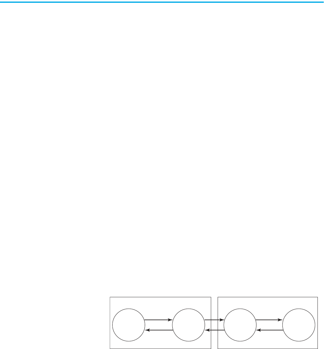
The following graphic shows how connections are layered on each other when
data is transferred over the EtherNet/IP network.
Rockwell Automation Publication ENET-UM006B-EN-P - May 2022 9
Chapter 1 EtherNet/IP Protocol
Remember these points when configuring your EtherNet/IP network
application:
• All connections are used each time data is transferred on the EtherNet/IP
network.
• You specify CIP connection message types and CIP connection types
when configuring your application.
For example, when a Logix 5000™ controller sends an MSG instruction to
another Logix 5000 controller, the transmitter sends the instruction to
the receiver over a connection. That connection includes the following:
- A TCP connection is established.
- A CIP connection is layered on the TCP connection.
- An explicit or implicit CIP connection message is delivered via the CIP
connection or via unconnected messaging.
- If an explicit message type is used, it can be connected or
unconnected. If an implicit message type is used, it is connected.
• Each EtherNet/IP communication module has TCP and CIP connection
limits that you must account for when configuring your application.
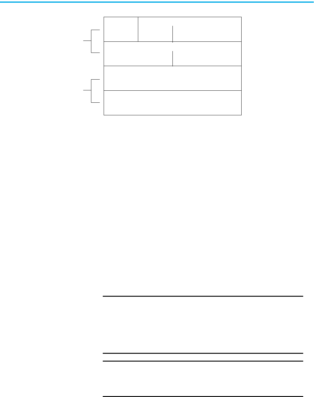
These example applications describe how connections are used.
TCP Connection
CIP Connection
Explicit Implicit
CIP Message Types
Connected
Connected
CIP Connection Types
Unconnected
You do not execute any tasks to
establish these connections.
Your decisions when configuring
your application determine the
parameters of these connections.
EXAMPLE
I/O Connections
A Logix 5000 controller has five CIP I/O connections to modules in a
remote chassis and all of these connections are through the same local
1756-EN2T module and the same remote 1756-EN2T module.
The following connections exist:
•One TCP connection
• Five CIP connections
EXAMPLE
RSLinx® OPC Test Client
The following connections exist:
•One TCP connection
• Four CIP connections (four is the default)

10 Rockwell Automation Publication ENET-UM006B-EN-P - May 2022
Chapter 1 EtherNet/IP Protocol
Terminology
The terms in this table help you understand connections.
TCP Connections
TCP connections are used for all EtherNet/IP communication and are
established before one device on the network transmits data to one or more
devices on the network. EtherNet/IP communication modules use one TCP
connection for each IP address to which the module is connected.
TCP connections are automatically established before CIP connections
because you can establish CIP connections only over a TCP connection. One
TCP connection supports multiple CIP connections.
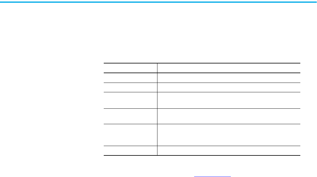
Table 1 - EtherNet/IP Connection Terminology
Term Definition
Producer and
consumer
Producer/Consumer refers to implicit connections. With implicit connections, messages are sent cyclically (every RPI).
EXAMPLE: Assume that a ControlLogix® controller is controlling one rack of FLEX™ I/O with a rack connection. Both the ENBT module that is local to the
controller and the FLEX AENT module are consumers and producers of data. The AENT consumes outputs and produces inputs.
Client and server
Client/server refers to explicit connections. A client creates a connection and initiates messages. A server provides a service or data. Clients can send
messages continuously or intermittently.
EXAMPLE: A ControlLogix controller can use an MSG instruction to communicate to another controller.
Transports
Each connection has transports. A transport is a uni-directional entity with its own numeric identifier. An implicit connection has 2 transports. An explicit
connection has 1 transport. Transports are important because they help you calculate the number of packets per second for each Ethernet interface.
EXAMPLE: I/O
For an I/O connection to a rack of distributed I/O, a connection is configured in the Logix Designer application by adding the communication adapter and I/
O modules in the I/O list. When the connection is created, output packets flow from the controller to the I/O rack. In addition, input packets flow from the I/
O to the controller. Each direction of flow is a transport. In this example, two transports exist. One transport is from the controller to the adapter. The
second transport is from the adapter to the controller.
EXAMPLE: Produced Tag
For a multicast produced tag connection with two consumers, there is a connection to each consumer. Data from the producer is produced to the wire on
one transport. Each of the consumers returns a heartbeat. A total of three transports exist in this example. One transport is from the tag producing
controller to the ‘wire’ media. The second transport is from one consumer to the tag producer. The third transport is from the second consumer.
UCMM
In the web servers, you can see references to Unconnected Message Manager (UCMM). This type of messaging is momentary and therefore can be ignored
unless you are troubleshooting. Examples of where UCMM messages are used are:
• Update of module firmware
• Some functions in RSLinx® software
• CIP Generic MSG instruction
• Opening any CIP connection (forward_open command)
IMPORTANT
EtherNet/IP communication modules also have web servers that use
TCP connections for non-CIP traffic, such as HTTP. However, TCP
connections that are used for non-CIP traffic do not count against the
limits that are mentioned in the preceding text.
Rockwell Automation Publication ENET-UM006B-EN-P - May 2022 11
Chapter 1 EtherNet/IP Protocol
CIP Connections
CIP connections are automatically established over a TCP connection and
transfer data from one device on the EtherNet/IP network to another. The
following are examples of CIP connections:
• Logix 5000 controller message transfer to another Logix 5000 controller
• I/O or produced tag
• Program upload, download, or going online
• Data acquisition from FactoryTalk® Linx and RSLinx® Classic
• PanelView™ polling of a Logix 5000 controller
There are different CIP connections.
CIP connections are further defined by these connection parameters:
• CIP Connection Message Types
• CIP Transport Types
CIP Connection Message Types
CIP connections use one of the following CIP connection message types:
• Implicit
• Explicit
Implicit connections are time critical in nature. These connections include I/O
and produced/consumed tags. Implicit refers to the data type and the meaning
of the data.
Explicit connections are non-time critical and are request/reply in nature.
Executing an MSG instruction or executing a program upload are examples of
explicit connections. Explicit refers to basic information (such as data type, or
meaning) that is included in every message.
Table 2 - CIP Connections
CIP Connection Description
Bridged
A bridged connection is a connection that passes through the EtherNet/IP communication module. The endpoint of the connection is
a module other than the EtherNet/IP communication module.
EXAMPLE: An explicit connection from a controller through a 1756-EN2T module to another controller.
End-node
An end-node connection is a connection whose endpoint is the EtherNet/IP communication module itself.
EXAMPLE: An explicit connection from RSLinx software to the EtherNet/IP communication module to set the module's IP address.
Rack-optimized
A rack-optimized connection is an implicit message connection to a rack or Assembly Object in the EtherNet/IP communication
module. Data from selected I/O modules is collected and produced on one connection (the rack-optimized connection) rather than
on a separate direct connection for each module.
This CIP connection is available with only digital I/O modules.
Direct
An implicit message connection from a controller to a specific I/O module (as opposed to a rack-optimized connection).
This CIP connection is available with analog and digital I/O modules.

12 Rockwell Automation Publication ENET-UM006B-EN-P - May 2022
Chapter 1 EtherNet/IP Protocol
CIP Transport Types
CIP transport types determine how CIP connections transfer data on the
network. The CIP transport types determine whether a connection is
established between devices.
There are two CIP transport types:
• Connected—Available with both implicit and explicit messages.
• Unconnected—Available with only explicit messages.
Table 3
describes how CIP connections are used with implicit and explicit
messages.
Table 3 - CIP Transport Types with Implicit and Explicit Messages
CIP Transport Type As Used with Implicit Messages As Used with Explicit Messages
Connected
The following events occur:
1. A connection is established between devices.
2. Data is transferred between devices.
3. The connection remains open for future data transmission.
The following are examples of connected implicit messaging:
• I/O data transfer
• Produced/consumed tags between Logix 5000 controllers
Keep in mind the following points for connected implicit messaging:
• Execution time is more efficient because the CIP connection between
devices does not need to be reopened for each data transfer.
• EtherNet/IP communication modules support limited numbers of CIP
connections. Because this connection is always open, there is one less
CIP connection available for other data transfer through the module.
The following events occur:
1. A connection is established between devices.
2. Data is transferred between devices.
3. The connection between the devices can be closed.
If data must be transferred again between these same two devices, the
connection must be reopened.
The following are examples of connected explicit messaging:
• MSG instruction
• RSLinx® Classic software setting the IP address for an EtherNet/IP
communication module
Keep in mind the following points for connected explicit messaging:
• Execution time is less efficient because the CIP connection between
devices must be reopened for each data transfer.
• EtherNet/IP communication modules support limited numbers of CIP
connections. Because this CIP connection is closed immediately after
use, the CIP connection is immediately available for other data transfer
through the module.
NOTE: If you select a cached connection, the connection is not closed at the
end of the transaction.
Unconnected —
In unconnected explicit messaging, no connection is established between
devices.
Data is sent in a packet that includes destination identifier information in
the data structure but does not have a dedicated CIP connection.

Rockwell Automation Publication ENET-UM006B-EN-P - May 2022 13
Chapter 1 EtherNet/IP Protocol
Packet Rate Capacity
The packet size impacts the implicit packet rate capacity of the ControlLogix
EtherNet/IP communication modules.
Smaller connections are processed faster than larger connections. Larger
connections can affect the increased packet rate capacity that is obtained with
firmware revision 3 or later. These types of applications use
larger connections:
(1)
• Applications with rack-optimized connections
• Applications with Integrated Motion on the EtherNet/IP network
• Applications with large produce/consume tag arrays
Modules with firmware revision 3 or later always have greater packet rate
capacity than modules with firmware revision 2 or earlier in the same
application. Larger connections impact only how much greater the packet rate
capacity is with firmware revision 3 or later.
Some EtherNet/IP communication modules offer webpages that show module
and application information such as capacity being used, in packets per
second. To view your module’s information, type the module’s IP address into
your web browser. See Appendix A
for more information.
Messaging
The EtherNet/IP network supports both time-critical (implicit) and non time-
critical (explicit) message transfer services of CIP. Exchange of time-critical
messages is based on the Producer/Consumer model where a transmitting
device produces data on the network and many receiving devices can consume
this data simultaneously.
Implicit Messages
Implicit messages are time critical in nature. These messages include I/O and
produced/consumed tags. Implicit refers to information (source address, data
type, and destination address) that is implied in the message, but not
contained in the message. Examples of implicit applications include the
following:
• Real-time I/O data
• Functional safety data
• Motion control data
Implicit messages use the User Datagram Protocol (UDP) and can be unicast
or multicast.
• The data source/destination is an application object (Assembly Object).
• There is no protocol in the message data—it is all I/O data.
• Data transfer is more efficient because the meaning of the data is known
ahead of time.
• Transfer is initiated on a time basis (cyclic trigger) or requested packet
interval (RPI).
• There is a connection timing mechanism to alert the application if the
other side has stopped communicating.
(1) Excludes the 1756-EN4TR.
14 Rockwell Automation Publication ENET-UM006B-EN-P - May 2022
Chapter 1 EtherNet/IP Protocol
•Messaging is always connected.
An implicit message times out in controller_multiplier x RPI. The multiplier is
selected by the controller firmware so that the timeout is greater than or equal
to 100 ms. The minimum multiplier is 4.
These are examples:
• RPI = 2 ms; controller multiplier = 64. The timeout is 128 ms.
• RPI = 10 ms; controller multiplier = 16. The timeout is 160 ms.
Explicit Messages
Explicit messages are non-time critical and are request/reply in nature.
Executing an MSG instruction or executing a program upload are examples of
explicit connections. Explicit refers to basic information (such as source
address, data type, or destination address) that is included in every message.
Each request is typically directed at another data item. Examples of explicit
applications include the following:
•HMI
• RSLinx connections
• Message (MSG) instructions
• Program upload/download
Explicit messages use TCP. Explicit messages are used for point-to-point,
client-server transactions.
• The server side is bound to the Message Router object and has access to
all internal resources.
• The client side is bound to a client application object and must generate
requests to the server.
• Explicit messages use an explicit messaging protocol in the data portion
of the message packet.
• Explicit messages can be connected or unconnected.
An explicit message times out in 30 seconds by default. This setting is user-
changeable in the Message (MSG) instruction structure.
Application
Object
Explicit
Messaging
Connection
Request
Response
Application
Object
Explicit
Messaging
Connection
Request
Response
Device #1 Device #2

Rockwell Automation Publication ENET-UM006B-EN-P - May 2022 15
Chapter 2
Ethernet Features in Network Devices
EtherNet/IP™ networks offer a comprehensive suite of messages and services
for many automation applications. This open network standard uses standard
Ethernet communication products to support real-time I/O messaging,
information exchange, and general messaging. All EtherNet/IP network
devices include the following features:
• Support for messaging, produced/consumed tags, and distributed I/O
• DNS addressing
• Internet Group Management Protocol (IGMP) snooping (enabled by
default) and querier (disabled by default)
• Port configuration and diagnostics
•Email server
EtherNet/IP supports CIP Safety™, CIP Motion™, and CIP Security™ at the
application layer.

16 Rockwell Automation Publication ENET-UM006B-EN-P - May 2022
Chapter 2 Ethernet Features in Network Devices
EtherNet/IP Device-Specific
Features
EtherNet/IP network devices can provide the following functionality. See the
user manual for your device for details.
• Supports various communication rates depending on your device
•Linear network
• Device Level Ring protocol
• Parallel Redundancy Protocol
• Duplicate IP address detection
• Socket interface
• Email client
Device Level Ring (DLR)
Device Level Ring (DLR) is an EtherNet/IP protocol defined by the Open
DeviceNet® Vendors’ Association (ODVA). DLR provides a means to detect, manage,
and recover from single faults in a ring-based network.
A DLR network includes the following types of ring nodes.
Depending on their firmware capabilities, both devices and switches can operate as
supervisors or ring nodes on a DLR network. Only switches can operate as redundant
gateways.
For more information about DLR, see the EtherNet/IP Device Level Ring
Application Technique, publication ENET-AT007
.
Node Description
Ring supervisor A ring supervisor provides these functions:
• Manages traffic on the DLR network
• Collects diagnostic information for the network
A DLR network requires at least one node to be configured as ring supervisor.
By default, the supervisor function is disabled on supervisor-capable devices.
Ring participants Ring participants provide these functions:
• Process data that is transmitted over the network.
• Pass on the data to the next node on the network.
• Report fault locations to the active ring supervisor.
When a fault occurs on the DLR network, ring participants reconfigure themselves and
relearn the network topology.
Redundant gateways
(optional)
Redundant gateways are multiple switches that connect to a single DLR network and
also connect together through the rest of the network.
Redundant gateways provide DLR network resiliency to the rest of the network.
Rockwell Automation Publication ENET-UM006B-EN-P - May 2022 17
Chapter 2 Ethernet Features in Network Devices
Parallel Redundancy
Protocol (PRP)
Parallel Redundancy Protocol (PRP) is defined in international
standard IEC 62439-3 and provides high-availability in Ethernet networks. PRP
technology creates seamless redundancy by sending duplicate frames to two
independent network infrastructures, which are known as LAN A and LAN B.
A PRP network includes the following components.
For more information about PRP, see the EtherNet/IP Parallel Redundancy Protocol
Application Technique, publication ENET-AT006
.
Component Description
LAN A and LAN B Redundant, active Ethernet networks that operate in parallel.
Double attached node (DAN) An end device with PRP technology that connects to both LAN A and LAN B.
Single attached node (SAN) An end device without PRP technology that connects to either LAN A or LAN B.
A SAN does not have PRP redundancy.
Redundancy box (RedBox) A switch with PRP technology that connects devices without PRP technology to
both LAN A and LAN B.
Virtual double attached node
(VDAN)
An end device without PRP technology that connects to both LAN A and LAN B
through a RedBox.
A VDAN has PRP redundancy and appears to other nodes in the network as a DAN.
Infrastructure switch A switch that connects to either LAN A or LAN B and is not configured as a RedBox.
18 Rockwell Automation Publication ENET-UM006B-EN-P - May 2022
Chapter 2 Ethernet Features in Network Devices
Duplicate IP Address
Detection
Duplicate IP address detection verifies that an IP address does not match any
other device IP address on the network when you perform either of these tasks:
• Connect the device to a EtherNet/IP network.
• Change the IP address on the device.
If the IP address matches that of another device on the network, the
EtherNet/IP port on the device transitions to conflict mode. In conflict mode,
these conditions exist:
• OK status indicator blinks red.
• Network (NET) status indicator is steady red.
• If the device has a text display, the following message scrolls across the 4-
character display:
<IP_address_of_this_device> Duplicate IP -
<MAC_address_of_duplicate_node_detected>
For example: 10.88.60.196 Duplicate IP - 00:00:BC:02:34:B4
Duplicate IP Address Resolution
This table describes how to resolve duplicate IP addresses.
Duplicate IP Address Detection Conditions Resulting Behavior
• Both devices support duplicate IP address detection
• Second device is added to the network after the first
device is operating on the network
1. The device that began operation first uses the IP address and continues to operate without interruption.
2. The device that begins operation second detects the duplication and enters Conflict mode.
• Both devices support duplicate IP address detection
• Both devices were powered up at approximately the same
time
Both EtherNet/IP devices enter Conflict mode.
To resolve this conflict, follow these steps:
a. Assign a new IP address to one of the devices.
b. Cycle power to the other device or disconnect and reconnect all Ethernet cables from the other device.
One device supports duplicate IP address detection and a
second device does not
1. Regardless of which device obtained the IP address first, the device that does not support IP address detection
uses the IP address and continues to operate without interruption.
2. The device that supports duplicate IP address detection detects the duplication and enters Conflict mode.

Rockwell Automation Publication ENET-UM006B-EN-P - May 2022 19
Chapter 2 Ethernet Features in Network Devices
DNS Addressing To qualify the device address further, use DNS addressing to specify a host
name for a device. When you specify a host name for the device, you also
specify a domain name and DNS servers. DNS addressing makes it possible to
create similar network structures and IP address sequences under different
domains.
DNS addressing is necessary only if you refer to the device by host name, such
as in path descriptions in MSG instructions.
To use DNS addressing, follow these steps.
1. Assign a host name to the device.
A network administrator can assign a host name. Valid host names
must be IEC-1131-3 compliant.
2. Configure the device IP address:
In the DNS server, the host name must match the IP address of
the device.
3. In the Logix Designer application, add the device to the I/O.
Socket Interface Some EtherNet/IP devices support the use of a CIP Generic MSG instruction to
request socket services. For more information, see EtherNet/IP Socket
Interface Application Technique, ENET-AT002
.
IMPORTANT
Make sure the DNS enable bit is set.
• If you use Logix Designer application, version 28 or later, to
configure your device, the enable bit is set and DNS addressing
is successful.
• If you use RSLinx® Classic software, version 2.41.00 or later, to
configure your device, the enable bit is cleared and DNS
addressing fails.
IMPORTANT
If a child device resides in the same domain as its parent device,
type the host name. If the domain name of the child device differs
from its parent device, type the host name and the domain name
(host.domain)
IMPORTANT
You can also use DNS addressing in a device profile in the I/O
configuration tree or in a message path. If the domain name of
the destination device differs from the source device, use a fully
qualified DNS name (hostname.domainname). For example, to
send a message from AEN2TR1.location1.companyA to
AEN2TR1.location2.company, the host names match, but the
domains differ. Without the entry of a fully qualified DNS name,
the device adds the default domain name to the specified host
name.
20 Rockwell Automation Publication ENET-UM006B-EN-P - May 2022
Chapter 2 Ethernet Features in Network Devices
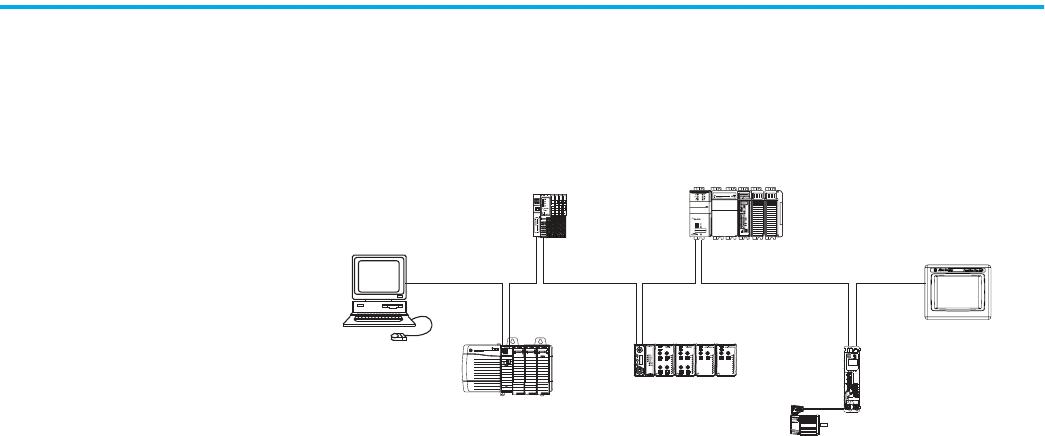
Linear Network A linear network is a collection of devices that are daisy chained together. The
EtherNet/IP embedded switch technology lets you implement this topology at
the device level. No additional switches are required.
Figure 1 - Example Linear Network
The following are advantages of a linear network.
• Simple installation
• Reduced wiring and installation costs
• No special software configuration required
• Improved CIP Sync application performance on linear networks
The primary disadvantage of a linear network is that any break of the cable
disconnects all devices downstream from the break from the rest of the
network.
2 (Rear)
00:00:BC:2E:69:F6
1 (Front)
U
V
W
2
1

Rockwell Automation Publication ENET-UM006B-EN-P - May 2022 21
Chapter 2 Ethernet Features in Network Devices
Device Level Ring Device Level Ring (DLR) is an EtherNet/IP protocol that is defined by ODVA.
DLR provides a means to detect, manage, and recover from single faults in a
ring-based network.
A DLR network includes the following types of ring nodes.
Depending on their firmware capabilities, both devices and switches can
operate as supervisors or ring nodes on a DLR network. Only switches can
operate as redundant gateways.
For more information about DLR, see the EtherNet/IP Device Level Ring
Application Technique, publication ENET-AT007
.
Node Description
Ring supervisor
A ring supervisor provides these functions:
• Manages traffic on the DLR network
• Collects diagnostic information for the network
A DLR network requires at least one node to be configured as ring supervisor.
IMPORTANT: By default, the supervisor function is disabled on supervisor-capable devices,
so they are ready to participate on a linear or star network or as a ring node on a DLR network.
In a DLR network, you must configure at least one of the supervisor-capable devices as the
ring supervisor before physically connecting the ring. If you do not, the DLR network does
not work.
Ring participants
Ring participants provide these functions:
• Process data that is transmitted over the network.
• Pass on the data to the next node on the network.
• Report fault locations to the active ring supervisor.
When a fault occurs on the DLR network, ring participants reconfigure themselves and relearn
the network topology.
Redundant gateways
(optional)
Redundant gateways are multiple switches that are connected to one DLR network and also
connected together through the rest of the network.
Redundant gateways provide DLR network resiliency to the rest of the network.
22 Rockwell Automation Publication ENET-UM006B-EN-P - May 2022
Chapter 2 Ethernet Features in Network Devices
EtherNet/IP Network
Specifications
Reserve 10% of the bandwidth (packets/second) of the network device for
temporary Explicit Messaging.
For other devices with EtherNet/IP connectivity, see the specifications in the
technical data for the device.
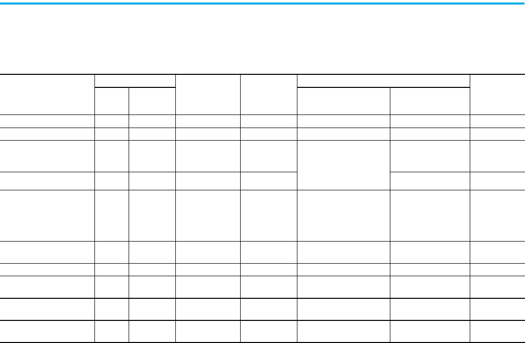
Table 4 - EtherNet/IP Network Specifications
Cat. No. Connections CIP Unconnected
Messages
(Backplane +
Ethernet)
Ethernet Node
Count, Max
Packet Rate Capacity (packets/second)
(1)
SNMP Support
(password
required)
TCP CIP I/O HMI and MSG
1734-AENT, 1734-AENTR 32 20 32 — 5000 900 No
1738-AENT, 1738-AENTR 32 20 32 — 5000 900 No
1756-EN2F, 1756-EN2T,
1756-EN2TXT, 1756-EN2TR,
1756-EN2TRXT
128
256
(2)
128 + 128 —
IMPORTANT: Packet rates for
ControlLogix EtherNet/IP
communication modules
depend on series and
firmware revision.
2000 Yes
1756-EN3TR 128
256
(2)
128 + 128 — 2000 Yes
1756-EN4TR, 1756-EN4TRXT 512
1000 I/O
528
(2)
256+256 —
• 50,000 without CIP Security
• 25,000 with integrity
• 15,000 with integrity and
confidentiality
• 3700 without CIP
Security
• 2700 with integrity
• 1700 with integrity and
confidentiality
Yes
1783-ETAP, 1783-ETAP1F, 1783-
ETAP2F
64 — — — — 900 No
1794-AENT 64 64 — — 9500 — Yes
5069-AENTR 32
16
(messaging)
16 — 100,000 500 Yes
5069-AEN2TR
256
(messaging)
32 — 100,000 2000 Yes
5094-AENTR, 5094-AENTRXT,
5094-AEN2TR, 5094-AEN2TRXT
32
16
(messaging)
16 — 100,000 500 Yes
(1) Total packet rate capacity = I/O Produced Tag, max + HMI/MSG, max. Packet rates vary depending on packet size. For more detailed specifications, see the EDS file for a specific catalog number.
(2) There are 1000 CIP I/O connections and 528 CIP messaging connections.

Rockwell Automation Publication ENET-UM006B-EN-P - May 2022 23
Chapter 2 Ethernet Features in Network Devices
Time Synchronization In certain situations, the I/O modules can synchronize with the adapter before
the adapter synchronizes with the system Grandmaster clock. This
synchronization occurrence leads to a time difference between the I/O and the
Grandmaster clock until the adapter synchronizes with the Grandmaster
clock.
In your logic, verify that the adapter is synchronized with the Grandmaster
clock before you initiate time stamp requests or scheduled outputs from your
I/O modules. A system with intermediate devices, such as network bridges and
switches, can require that you insert a delay until the time stabilizes in the
system.
For information on how to verify that the adapter is synchronized to a
Grandmaster clock, see CIP Sync Diagnostics in the Integrated Architecture®
and CIP Sync Configuration Application Technique, publication IA-AT003
.
This publication also includes information on Time Sync Object Attributes.
Simple Network
Management Protocol
(SNMP)
SNMP enables an Ethernet switch to be remotely managed through other
network management software. SNMP defines the method of communication
among the devices and also denotes a manager for the monitoring and
supervision of the devices. Confidential information can be encrypted to help
prevent the contents from being exposed on the network. For more
information, see the SNMP Password and MIB Configuration
Knowledgebase
article.

24 Rockwell Automation Publication ENET-UM006B-EN-P - May 2022
Chapter 2 Ethernet Features in Network Devices
Notes:
Rockwell Automation Publication ENET-UM006B-EN-P - May 2022 25
Chapter 3
Configure a Workstation to Operate on an
EtherNet/IP Network
Before you can connect to the device via an Ethernet cable, you must install an
EtherNet/IP™ driver on your workstation.
A communication driver is required to complete these tasks:
• Upload and download controller projects over an EtherNet/IP network.
• Collect controller data for electronic operator interfaces, for example,
PanelView™ Plus terminals, and visualization software, for example,
FactoryTalk
®
View software
• Update device firmware
• Set or change the IP address.
•Configure the device
When you are configuring your software, consider the details in Table 5
.
Table 5 - Configuration Software Descriptions
Configuration Software Description
FactoryTalk® Linx™
FactoryTalk® Linx™ is a FactoryTalk Live Data server and communications service designed
to deliver control system information from Allen-Bradley® control products to the Rockwell
Automation FactoryTalk® software portfolio and Studio 5000® design software.
FactoryTalk Linx is specifically optimized to work with Logix 5000™ Programmable
Automation Controllers (PAC) and the PlantPAx® process controller.
Prior to version 6.00 FactoryTalk Linx was called RSLinx® Enterprise. Because of this, some
portions of the software installation and documentation still contain references to the
previous RSLinx Enterprise name.
RSLinx Classic
®
RSLinx Classic links Allen-Bradley networks and devices to Microsoft Windows applications.
RSLinx Classic also incorporates advanced data optimization techniques and contains a set
of diagnostics. RSLinx Classic is an OPC DA (Data Access) Compliant Server and a DDE server.
26 Rockwell Automation Publication ENET-UM006B-EN-P - May 2022
Chapter 3 Configure a Workstation to Operate on an EtherNet/IP Network
Configure the Ethernet
Communication Driver in
FactoryTalk Linx Software
FactoryTalk Linx software supports the following communication drivers:
Before you add an Ethernet driver, confirm that these conditions exist:
• The workstation is properly connected to the EtherNet/IP network.
• The workstation IP address and other network parameters are
configured correctly.
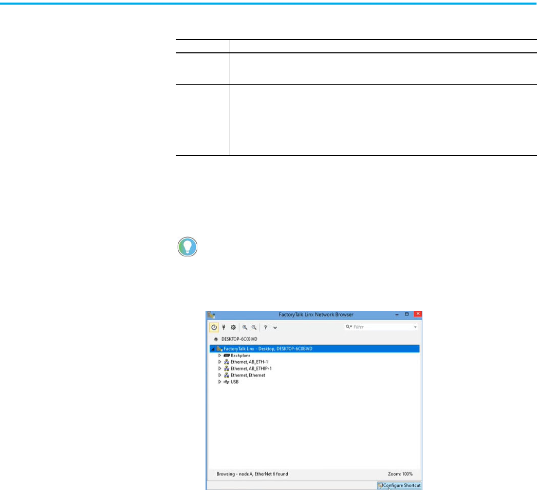
Open FactoryTalk Linx network browser either from within your
programming application or from Start > Rockwell Software > FactoryTalk
Linx network browser.
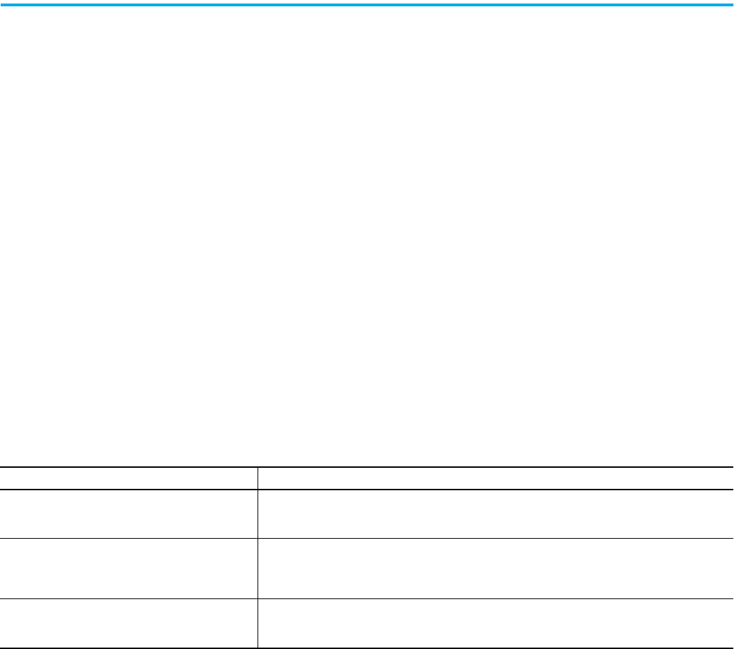
Driver Description
Ethernet
Provides an option to broadcast device discover or option to specific device list / range
Supports runtime communications
Supports communications over longer distances when compared to the USB driver.
USB Driver
Three drivers are automatically created using configurations from earlier versions of Linx software.
The USB is populated when a USB cable is connected to a device capable of supporting CIP
Lets you:
• Connect to an unconfigured device and configure an Ethernet port.
• Update the device firmware
Not intended for runtime connections; it is a temporary-use only connection with a limited cabling
distance.
CIP™ Security is available through FactoryTalk
®
Linx, version 6.11 or later.
Rockwell Automation Publication ENET-UM006B-EN-P - May 2022 27
Chapter 3 Configure a Workstation to Operate on an EtherNet/IP Network
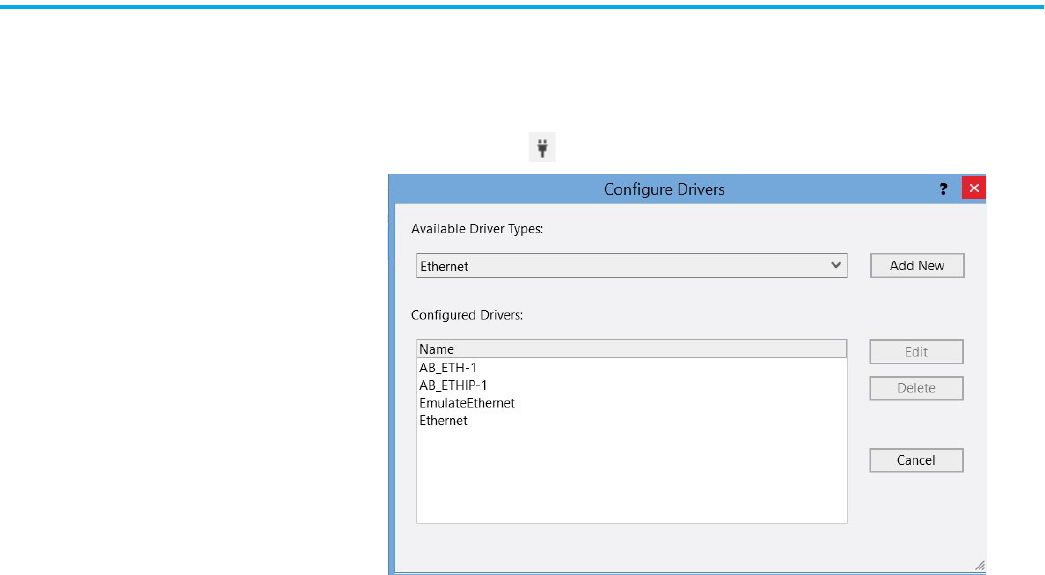
FactoryTalk Linx creates two Ethernet drivers by default.
With FactoryTalk Linx, you can:
• Specify a single IP address or a range of IP addresses for the AB-Ethernet
driver.
• Create a new driver.
Table 6 - Ethernet Drivers
Driver Description
Ethernet, AB_ETH-1
Enables the FactoryTalk Linx Network Browser to target a device that is configured to block
remote broadcast messages. The list can contain a maximum of 255 IP addresses specified
individually or as a range. If you are using an IP address range, each IP address in the range
can be assigned to a device. Unattached IP addresses can delay broadcast messages and
can create additional network messages.
Ethernet, AB_ETHIP-1
• Broadcast - enables the FactoryTalk Linx Network Browser to sends a UDP broadcast
message to all devices on a local or remote subnet.
• Local - enables the FactoryTalk Linx Network Browser to send a UDP broadcast message
to all devices on the same subnet that is connected to the computer.
• Remote - enables the FactoryTalk Linx Network Browser to target the UDP broadcast to
another subnet on the network determined the IP address and subnet mask you provide.
• In some cases, the default Ethernet Switch configuration blocks a remote UDP broadcast
message from being propagated to a subnet, and no devices are detected. If this occurs,
use the Device List/Range discovery method.
When a local or remote UDP broadcast discovery message is transmitted, each device
responds with their individual identity information. Avoid using this driver configuration if
you have a subnet with a high number of devices or if the network is heavily loaded. When
adding new drivers, the FactoryTalk Linx Network Browser defaults to Local Broadcast
Configuration.
28 Rockwell Automation Publication ENET-UM006B-EN-P - May 2022
Chapter 3 Configure a Workstation to Operate on an EtherNet/IP Network
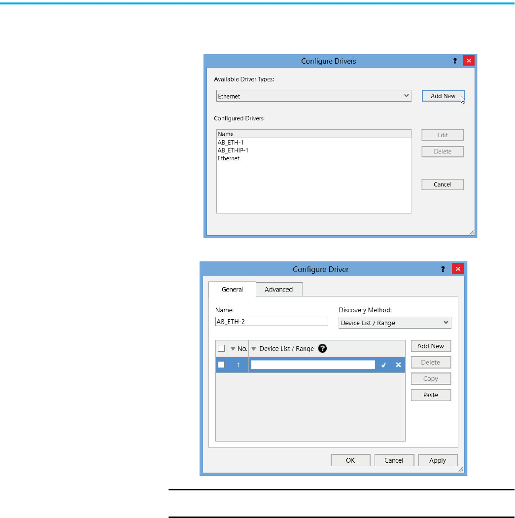
Specify a Single IP Address or a Range of IP Addresses
1. Select the Ethernet, AB_Eth1 driver and select Driver Configuration.
2. The following image appears when you click Add New.
IMPORTANT IP Addresses in a range that do not exist on the network result in extra
network traffic.
Rockwell Automation Publication ENET-UM006B-EN-P - May 2022 29
Chapter 3 Configure a Workstation to Operate on an EtherNet/IP Network
Add a New Driver
1. Select the Backplane or an existing driver.
Select the plug icon and select Add New.
2. Enter the information for the new driver.
The new driver follows the same list and broadcast options as the
AB_ETH1 driver.
30 Rockwell Automation Publication ENET-UM006B-EN-P - May 2022
Chapter 3 Configure a Workstation to Operate on an EtherNet/IP Network
Configure the Ethernet
Communication Driver in
RSLinx Classic Software
RSLinx Classic software supports the following communication drivers:
Before you add an Ethernet driver, confirm that these conditions exist:
• The workstation is properly connected to the EtherNet/IP network.
• The workstation IP address and other network parameters are
configured correctly.
Open RSLinx Classic software either from within your programming
application or from Start > Rockwell Software > RSLinx Classic.
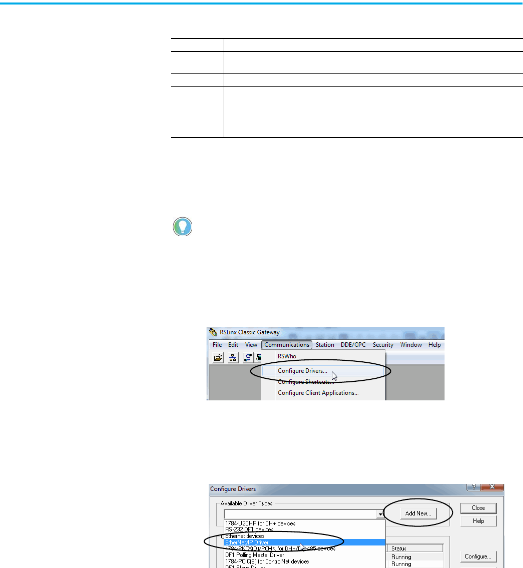
To configure the EtherNet/IP driver, follow these steps.
1. From the Communications menu, choose Configure Drivers.
The Configure Drivers dialog box appears.
2. From the Available Driver Types pull-down menu, choose
EtherNet/IP Driver.
3. Click Add New.
The Add New RSLinx® Driver dialog box appears.
Driver Description
EtherNet/IP
Supports runtime communications
Supports communications over longer distances when compared to the USB driver
Ethernet Lets you manually configure the IP addresses for devices.
USB Driver
Lets you:
• Connect to an unconfigured device and configure an Ethernet port.
• Update the device firmware
Not intended for runtime connections; it is a temporary-use only connection with a limited cabling
distance.
If you need to use CIP™ Security, it is only available through FactoryTalk
®
Linx,
version 6.11 or later.
Rockwell Automation Publication ENET-UM006B-EN-P - May 2022 31
Chapter 3 Configure a Workstation to Operate on an EtherNet/IP Network
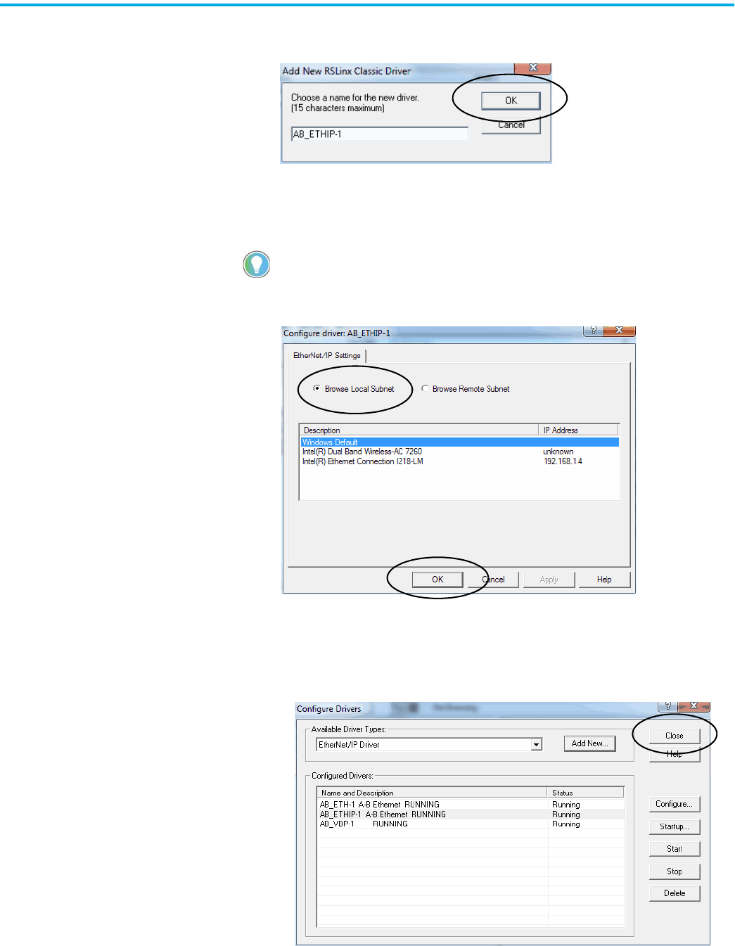
4. Type a name for the new driver and click OK.
The Configure driver dialog box appears.
5. Click Browse Local Subnet.
6. Select the desired driver, and click OK.
The new driver is available on the Configure Drivers dialog box.
7. Click Close.
To view devices on another subnet or VLAN from the workstation
running RSLinx Classic software, click Browse Remote Subnet.

32 Rockwell Automation Publication ENET-UM006B-EN-P - May 2022
Chapter 3 Configure a Workstation to Operate on an EtherNet/IP Network
Notes:

Rockwell Automation Publication ENET-UM006B-EN-P - May 2022 33
Chapter 4
Set an IP Address
There are multiple ways to set an IP address. Check the user documentation
for your device for the preferred method.
• EtherNet/IP™ Address Commissioning Tool
• FactoryTalk® Linx Network Browser software
• Studio 5000 Logix Designer® Application
• BOOTP/DHCP tool
• RSLinx® Classic software
• Hardware switches
Set the IP Address with the
EtherNet/IP Address
Commissioning Tool
You can use the EtherNet/IP Address Commissioning Tool to:
• Assign the IP address, subnets, and other parameters to BOOTP and
DHCP enabled devices.
• For EtherNet/IP or CIP™ connected devices, change the device operation
between dynamic mode where the device initiates BOOTP/DHCP
request to static mode where BOOTP/DHCP requests are disabled and
communications settings within the device are used.
• Set and modify the IP addresses of EtherNet/IP devices with known MAC
addresses, but unknown IP addresses.
The BOOTP/DHCP IP address assignment process begins when a device
without an IP address powers up. The device initiates a BOOTP/DHCP request
that contains the device's Media Access Control (MAC) address onto the
network as a broadcast message. If the network switches are configured to
support broadcast and BOOTP/DHCP messages (many managed switches
disable this capability), a BOOTP/DHCP server receives the request,
determines the appropriate IP address for the device and responds with an IP
address assignment.
If the device does not receive a response in an appropriate amount of time, it
waits a random amount of time and retries the request. After each failed
attempt, the retries become less frequent. A device configured to use
BOOTP/DHCP typically resets or loses its IP address assignment when
powered down, unless its settings are modified to change it out of dynamic
BOOTP/DHCP mode to static mode.
34 Rockwell Automation Publication ENET-UM006B-EN-P - May 2022
Chapter 4 Set an IP Address
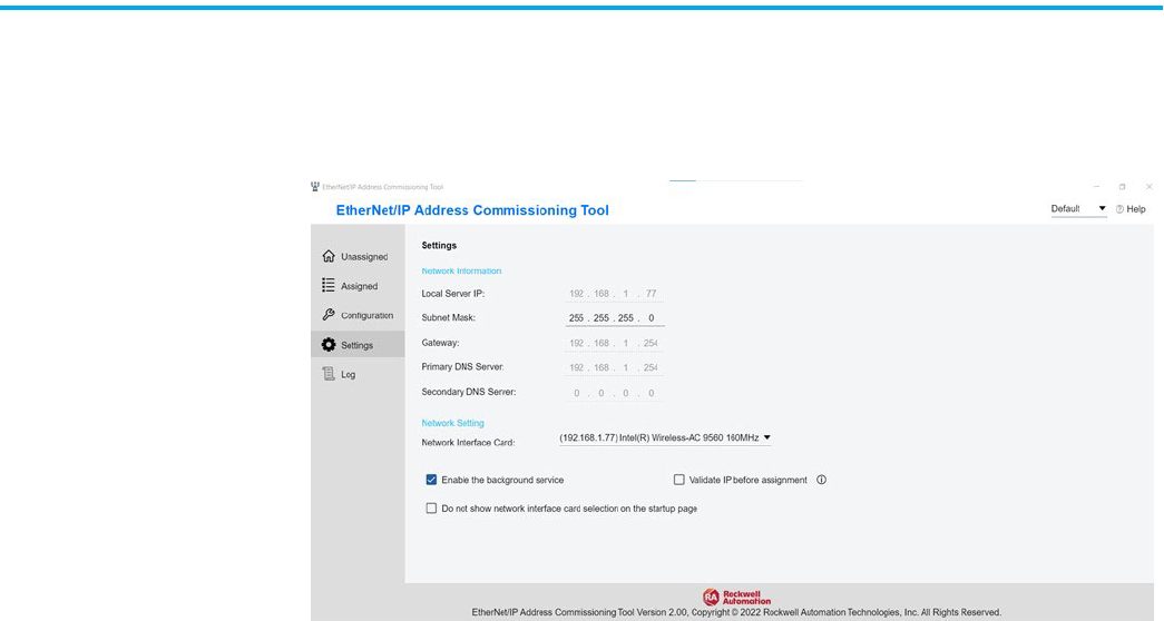
Set Up the Tool
1. Open the EtherNet/IP Address Commissioning Tool and select the
network interface card for your workstation.
2. Open Settings to define how the tool operates.
If a multiple network interfaces card (NICs) exists, the EtherNet/IP Address
Commissioning Tool can only interact with one of them.
Rockwell Automation Publication ENET-UM006B-EN-P - May 2022 35
Chapter 4 Set an IP Address
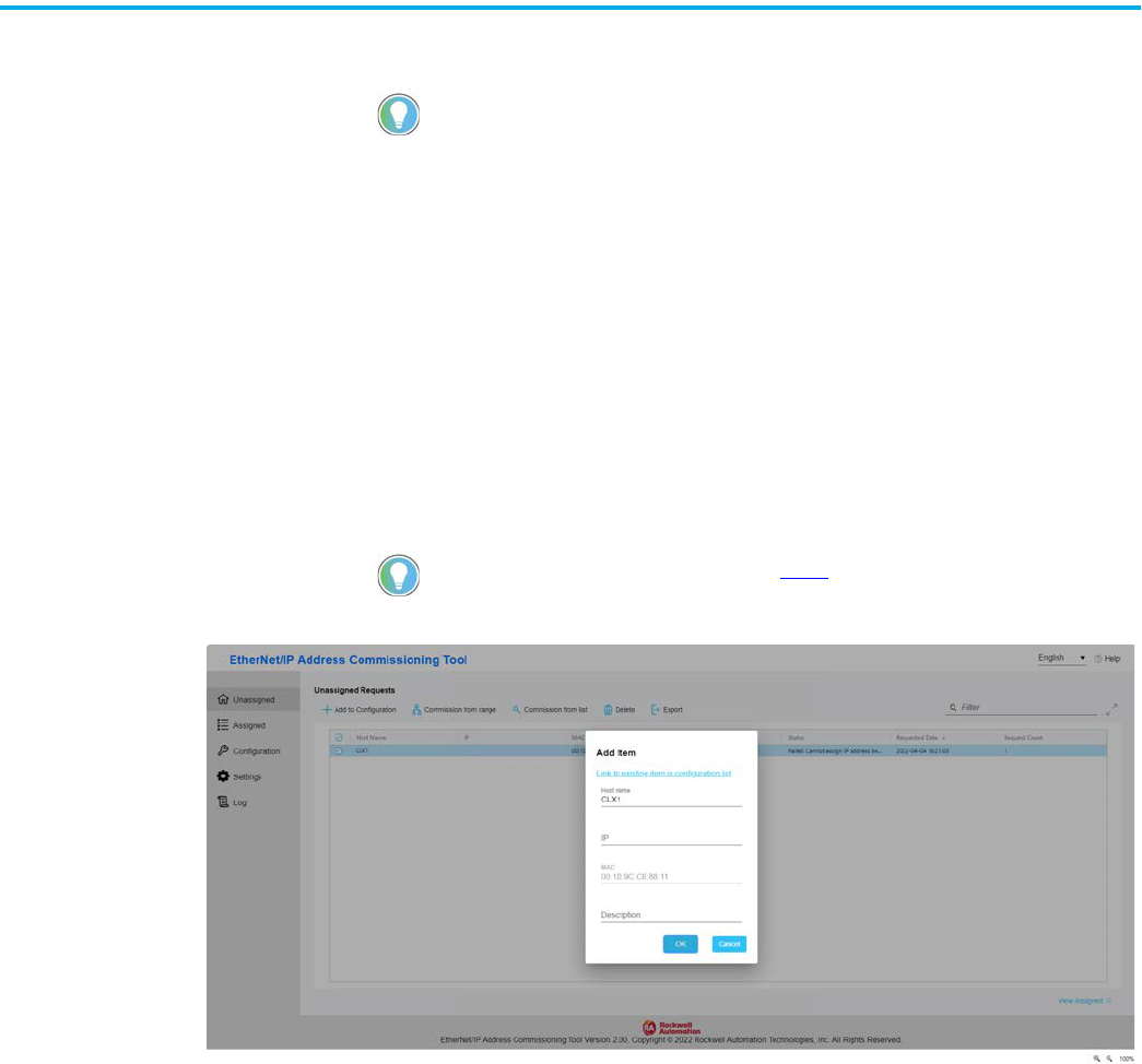
Assign IP Addresses Manually
The Unassigned tab lists the devices that have not been assigned an IP address.
Use the Unassigned tab to configure the IP address or set up rules for
automatic IP assignment.
When a BOOTP/DHCP is requested and the MAC address is not found in the
configuration list, the device appears in the Unassigned list.
1. Select Add to Configuration to manually enter the information for a
device into the configuration list.
The IP address is offered the next time that the device makes a
BOOTP/DHCP request. This function is similar to how the
BOOTP/DHCP tool operates.
2. Wait for the device to make a subsequent BOOTP/DHCP request.
There are many computer and network configuration scenarios that can affect
this process. If an error is reported, review the troubleshooting section in tool
online help.
To choose an existing IP address, move to step 4.
36 Rockwell Automation Publication ENET-UM006B-EN-P - May 2022
Chapter 4 Set an IP Address
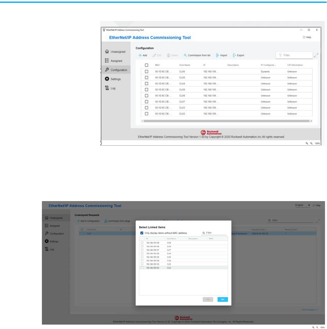
3. The device now appears on the Assigned Tab.
4. If you are linking to an existing item, click “Link to existing item in
configuration list”.
Now you can select an item that does not have an exisiting MAC address.
You can also remove any checks from a selected check box and replace an
existing item.
Rockwell Automation Publication ENET-UM006B-EN-P - May 2022 37
Chapter 4 Set an IP Address
Once you click a list item, and select “Yes”, the details automatically
populate the previous dialog box.
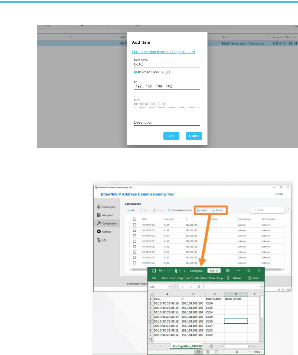
Options to make assigning IP addresses more streamlined include:
• Import a list of IP addresses in the Configuration tab and merge them
with incoming requests.
38 Rockwell Automation Publication ENET-UM006B-EN-P - May 2022
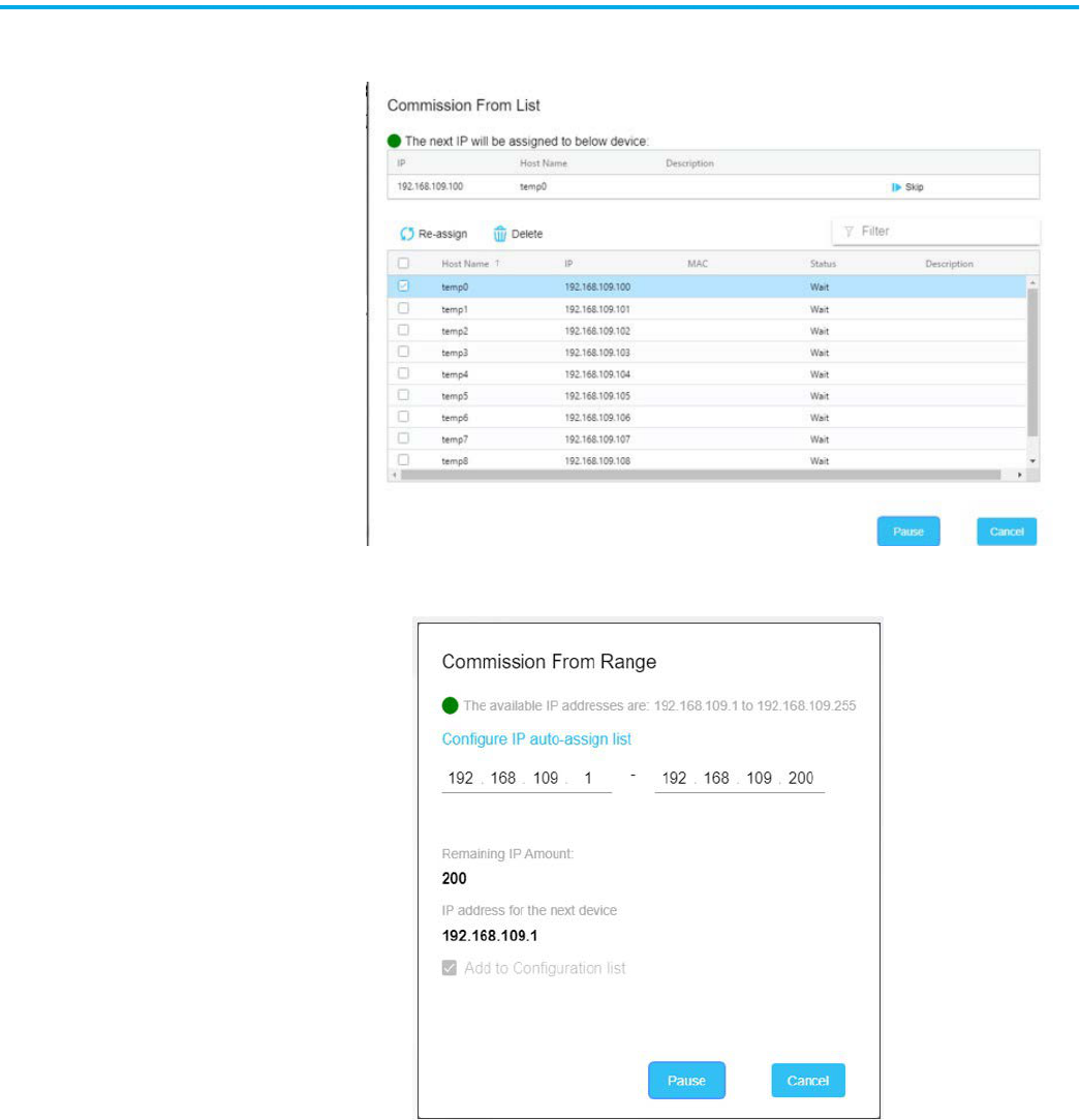
Chapter 4 Set an IP Address
• Use imported addresses with the Commission from List Feature to
indicate the order to bring devices online.
• Use the Commission from Range feature option to automatically assign
IP addresses to a preset range you provide.
Rockwell Automation Publication ENET-UM006B-EN-P - May 2022 39
Chapter 4 Set an IP Address
Set the IP Address with
FactoryTalk Linx Software
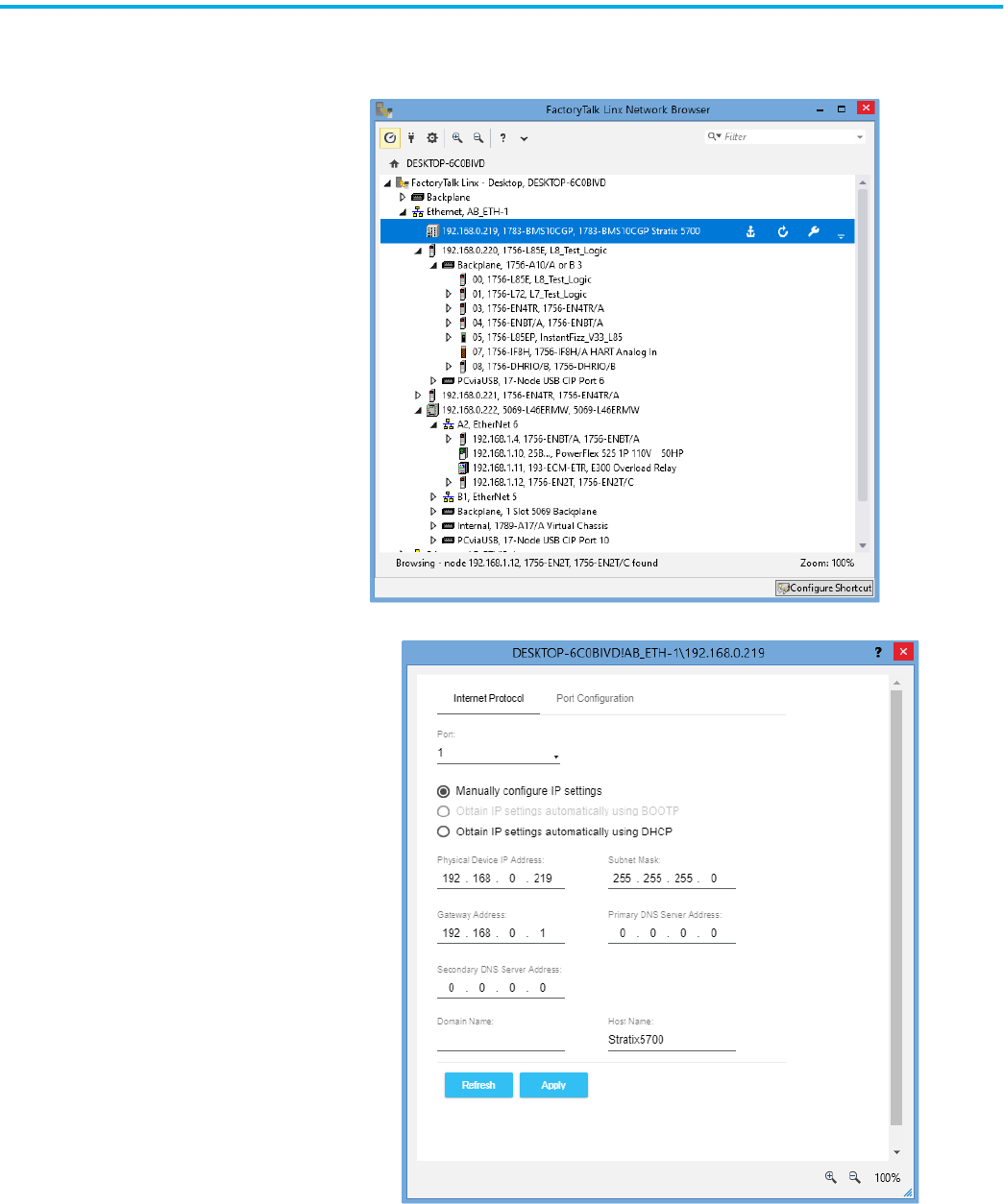
To use FactoryTalk Linx software to set the IP address, follow these steps.
1. Open the FactoryTalk Linx Network Browser and browse to the device.
2. To set the IP address, click the wrench.
40 Rockwell Automation Publication ENET-UM006B-EN-P - May 2022
Chapter 4 Set an IP Address
Set the IP Address with
Studio 5000 Logix Designer
Application
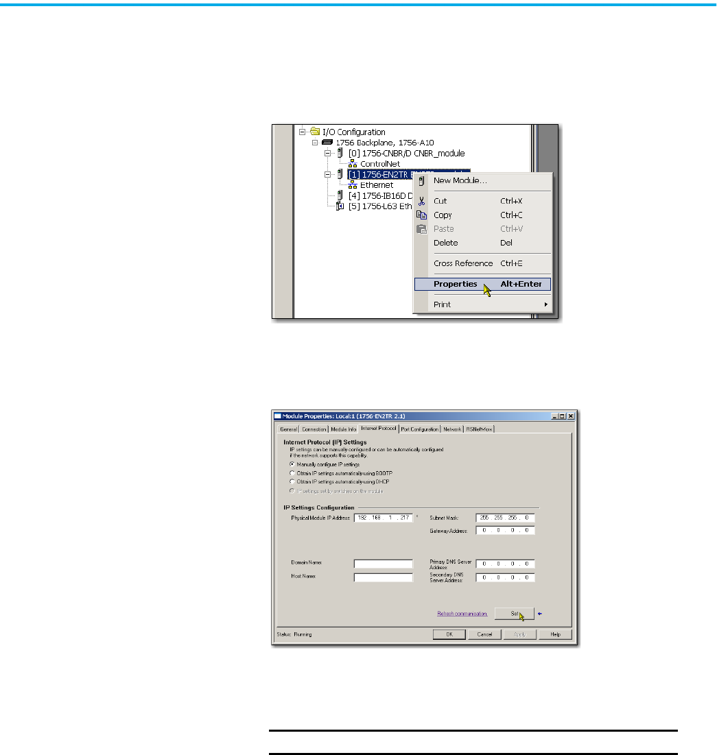
To use the Logix Designer application to set the IP address of the device, follow
these steps.
1. In Logix Designer, Go Online.
2. In the Controller Organizer, right-click the device and choose Properties.
The Module Properties dialog box appears.
3. Click the Internet Protocol tab.
4. Select Manually configure IP Settings radio button, then type the IP
address in the IP address field.
5. In the other fields, type the other network parameters, if needed.
6. Click Set.
7. Click OK.
IMPORTANT
The fields that appear vary from one device to another.
Rockwell Automation Publication ENET-UM006B-EN-P - May 2022 41
Chapter 4 Set an IP Address
Set the IP Address with
RSLinx Classic Software
You can use RSLinx Classic software to configure the device, including to
change the IP address after it has been set.
If you want to use RSLinx Classic software to set the IP address for the first
time (after it powers up in the out-of-box state), follow these steps.
1. Set the IP address switches on the device to anything other than
000…255)
Do not use 888: that address is reserved for a factory reset in some
devices.
Check with your device to verify that other addresses are not reserved by
your device for other features.
2. Connect to the device via the USB port.
If the device does not have a USB port, you cannot use RSLinx Classic
software to set the IP address for the first time the device powers up in
the out-of-box state.
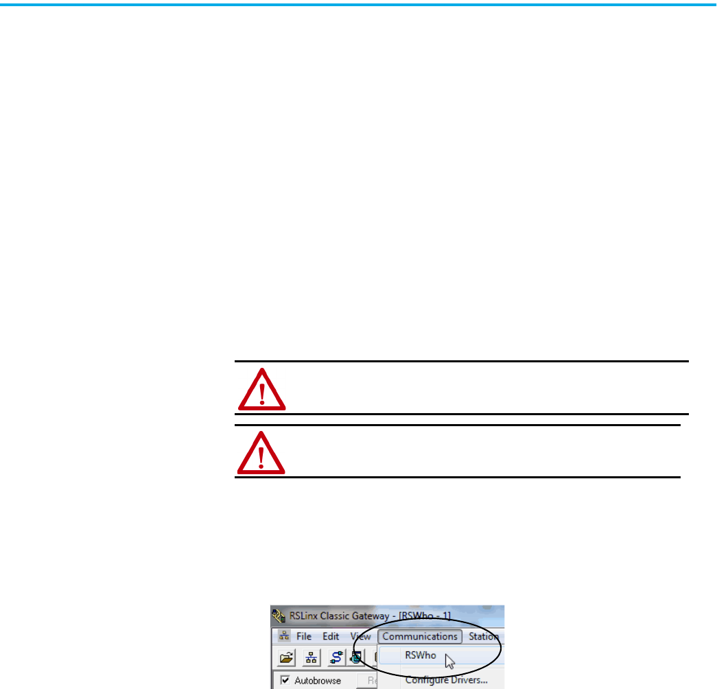
3. Start the RSLinx Classic software.
After several seconds, an RSWho dialog box appears.
4. If the RSWho dialog box does not appear, from the Communications
pull-down menu, choose RSWho.
WARNING: Do not use the USB port in hazardous locations.
ATTENTION: The USB port is intended for temporary local programming
purposes only and not intended for permanent connection. The USB
cable is not to exceed 3.0 m (9.84 ft) and must not contain hubs.
42 Rockwell Automation Publication ENET-UM006B-EN-P - May 2022
Chapter 4 Set an IP Address
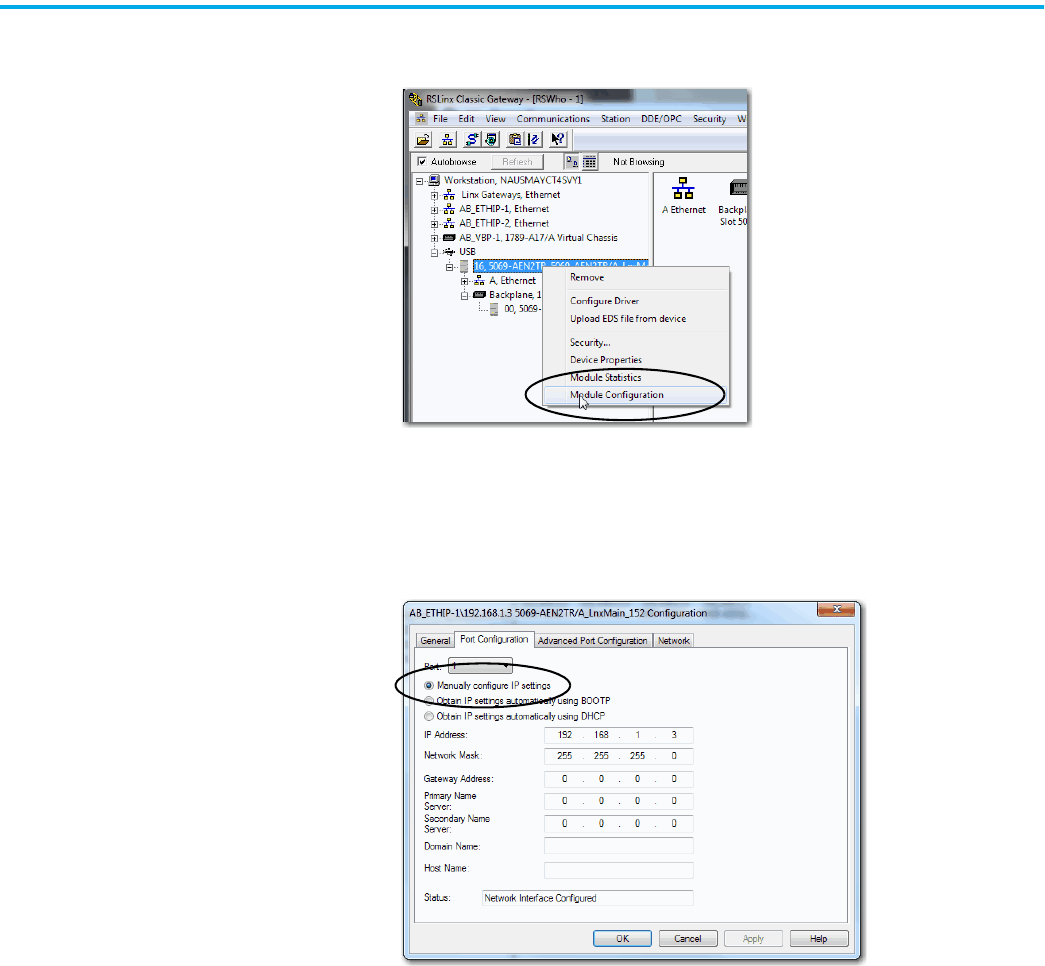
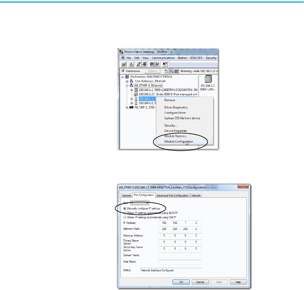
5. Right-click the device and choose Module Configuration.
The Module Configuration dialog box appears.
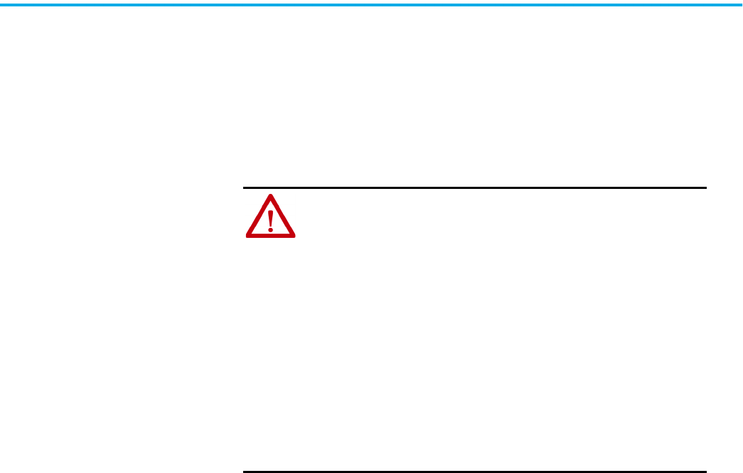
6. Click the Port Configuration tab.
7. Click Manually configure IP settings and set the port configuration
parameters.
8. Click OK.
9. Open the USB branch on the menu tree.
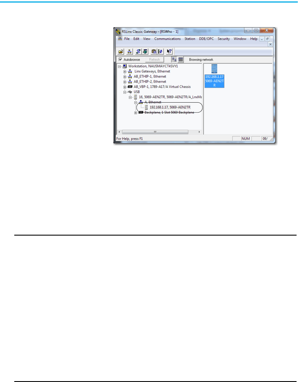
Rockwell Automation Publication ENET-UM006B-EN-P - May 2022 43
Chapter 4 Set an IP Address
The device shows the IP address.
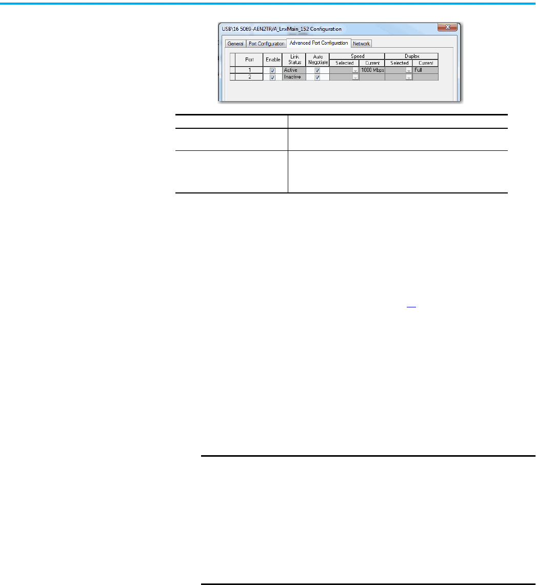
Configure Port Settings with RSLinx Classic Software
You can use RSLinx Classic software to configure a subset of the parameters
available on the device.
Complete the following steps.
1. Right-click the device and then click Module Configuration.
2. Click the Advanced Port Configuration tab.
IMPORTANT
Consider the following when you configure the port settings:
• When the device uses the 1 Gbps network communication rate, it supports only full-duplex mode.
• When the device uses the 10 Mbps or 100 Mbps network communication rate, it supports full-duplex and half-duplex
mode.
• The speed and duplex settings for the devices on the same Ethernet network must be the same to avoid transmission
errors.
• Fixed speed and full-duplex settings offer better reliability than autonegotiate settings and are recommended for
some applications.
• If the device is connected to an unmanaged switch, leave Auto-negotiate checked or the device fails.
• If you force the port speed and duplex with a managed switch, the corresponding port of the managed switch must
be forced to the same settings or the device fails.
• If you connect a manually configured device to an autonegotiate device (duplex mismatch), a high rate of
transmission errors can occur.
• To disable a port, clear the Enable checkbox.
On some DLR devices you cannot disable both ports simultaneously in RSLinx Classic software. We recommend that
before you disable a port, you confirm that the port is not in use.
• If you disable a port in RSLinx Classic software and the port is being used for network communication, the
communication is interrupted.
In this case, if the other Ethernet port is enabled, we recommend that you moved the Ethernet cable from the
disabled port and connect it to the enabled port.
After you re-enable the port that was unintentionally disabled, you can change the cable connection back to the first
port
44 Rockwell Automation Publication ENET-UM006B-EN-P - May 2022
Chapter 4 Set an IP Address
3. On the Module Configuration dialog box, click OK.
Set the IP Address with the
BOOTP/DHCP Tool
The BOOTP/DHCP tool is a standalone server that you can use to set an IP
address. The BOOTP/DHCP tool sets an IP address and other TCP parameters.
The EtherNet/IP Address Commissioning Tool provides additional
functionality than the BootP/DHCP tool. See page 33
.
You can use the BOOTP/DHCP tool to set the IP address when the device
powers up in the out-of-box state. The out-of-box state would assume the
rotary switches, if present on the device, are not set to a valid IP address, and
the device is DHCP enabled.
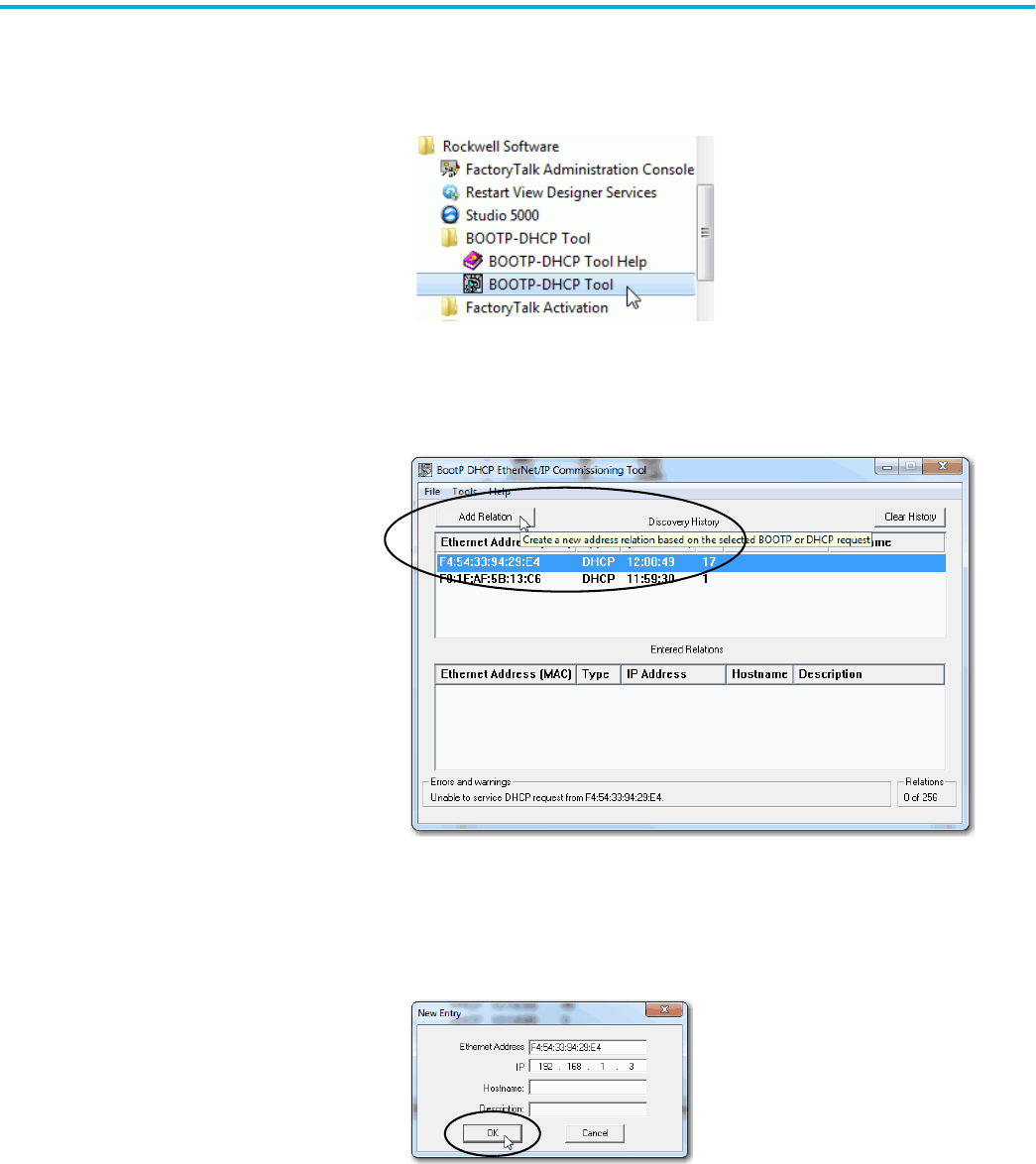
Access the BOOTP/DHCP tool from one of these locations:
• Programs > Rockwell Software® > BOOTP-DHCP Tool > BOOTP-DHCP
Tool
• Tools directory on the Studio 5000® environment installation CD
Task Action
Let the device automatically set the
port speed and duplex settings.
Leave the Auto-negotiate enabled.
Manually configure the port speed
and duplex settings.
Follow these steps.
1. Clear the Auto-negotiate port speed and duplex checkbox.
2. From the Current Port Speed pull-down menu, choose a port speed.
3. From the Current Duplex pull-down menu, choose full-duplex.
IMPORTANT
Before you start the BOOTP/DHCP tool, remember the following:
• Make sure that you have the hardware (MAC) address of the device.
The hardware address is on a sticker on the side of the device and
has a format similar to the following:
00-00-BC-14-55-35
• Make sure that the workstation that you use to set the IP address has
only one connection to the EtherNet/IP™ network on which the device
resides.
The BOOTP/DHCP tool can fail to work if your workstation has multiple
connections to the EtherNet/IP network.
Rockwell Automation Publication ENET-UM006B-EN-P - May 2022 45
Chapter 4 Set an IP Address
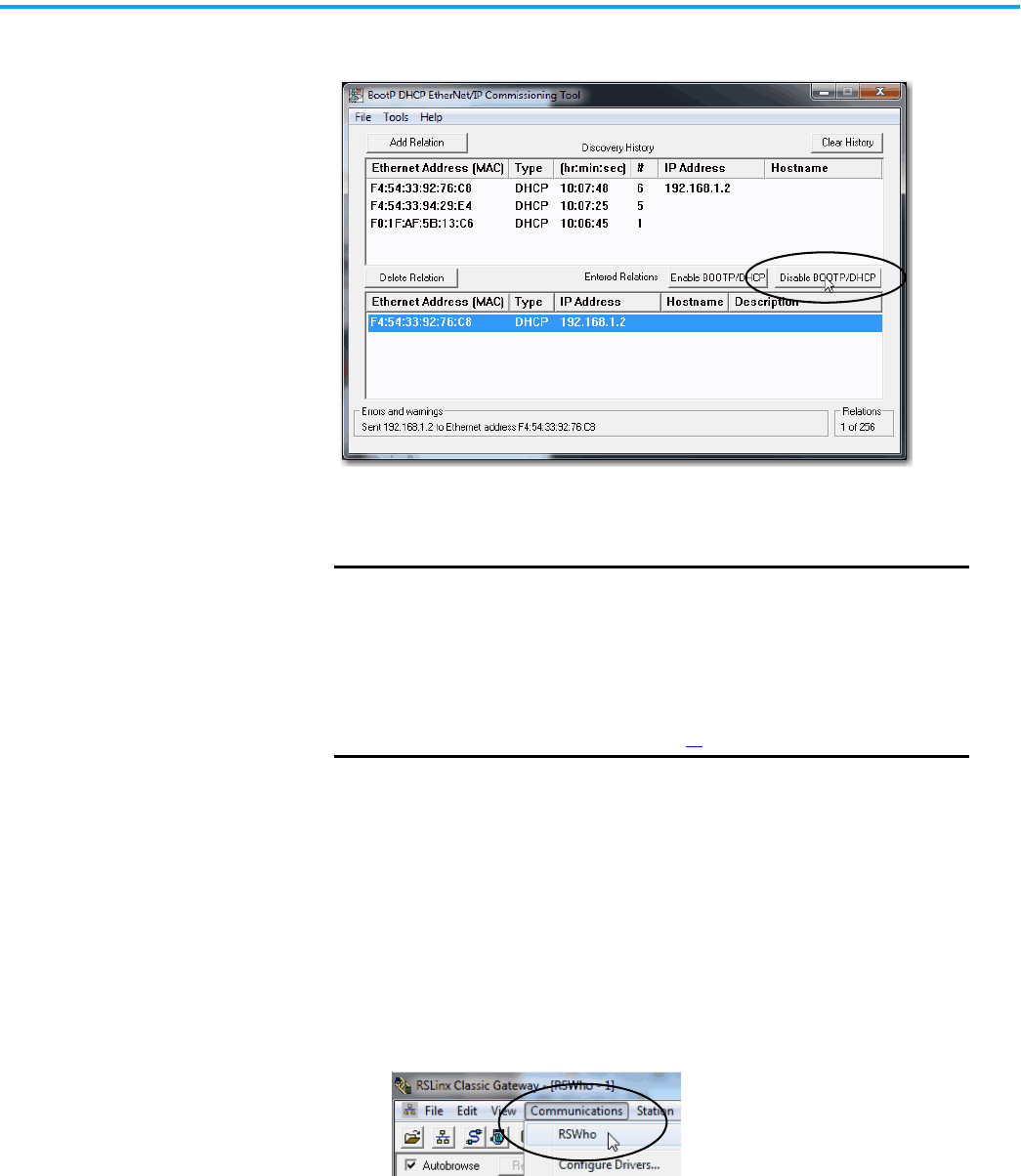
To set the IP address with BOOTP/DHCP tool, complete the following steps.
1. Confirm that the device is connected to the network.
2. Start the BOOTP-DHCP tool.
The MAC ID of the device appears in the Request History window.
3. Select the appropriate device and click Add to Relation List.
The New Entry dialog box appears.
4. Type an IP address, Hostname, and Description for the device.
Hostname and Description are optional.
5. Click OK.
6. To assign this configuration on the device, wait for the device to appear
in the Relation List panel and select it.
46 Rockwell Automation Publication ENET-UM006B-EN-P - May 2022
Chapter 4 Set an IP Address
7. Click Disable BOOTP/DHCP.
The device now uses the assigned configuration and does not issue BOOTP or
DHCP requests after power is cycled on the controller.
Disable BOOTP/DHCP with RSLinx Classic Software
To disable BOOTP/DHCP in RSLinx Classic software, complete the following
steps.
1. Start RSLinx Classic software.
After several seconds, an RSWho dialog box appears.
2. If no RSWho dialog box appears, from the Communications pull-down
menu, choose RSWho.
IMPORTANT
Remember the following:
• If you do not click Disable BOOTP/DHCP, on future power cycles, the
current IP configuration is cleared and the controller sends DHCP
requests again.
• If you click Disable BOOTP/DHCP and it does not disable BOOTP/DHCP,
you can use RSLinx® Classic software to disable BOOTP/DHCP.
For more information on how to use RSLinx Classic software to
disable BOOTP/DHCP, see page 46
.
Rockwell Automation Publication ENET-UM006B-EN-P - May 2022 47
Chapter 4 Set an IP Address
3. Navigate to the device.
You can access the device via the USB or an EtherNet/IP driver.
4. Right-click on the device and choose Module Configuration.
5. Click the Port Configuration tab.
6. Click Manually configure IP settings.
7. Click OK.
48 Rockwell Automation Publication ENET-UM006B-EN-P - May 2022
Chapter 4 Set an IP Address
DHCP Considerations
If the device is DHCP-enabled in the out-of-box condition, you can use a DHCP
server to set the IP address.
The DHCP server automatically assigns IP addresses to client stations logging
on to a TCP/IP network. DHCP is based on BOOTP and maintains some
backward compatibility.
Set the IP Address with
Hardware Switches
The devices ship set to 999. To change the IP address, do the following.
1. To change the number, use the rotary or thumbwheel switches on your
device.
2. Use a Dynamic Host Configuration Protocol (DHCP) server, such as
BootP/DHCP.
3. Retrieve the IP address from nonvolatile memory.
The device reads the rotary or thumbwheel switches first to determine if the
switches are set to a valid number. Valid settings range from 001…254.
When you assign an address and set it to 001, the gateway address is set to
0.0.0.0. and the subnet mask is 255.255.255.0. When you assign an address
between 002...254, the gateway address is set to 192.168.1.1 and the subnet mask
is set to 255.255.255.0.
If DHCP is not enabled, the device uses the IP address, along with other TCP
configurable parameters, which are stored in nonvolatile memory.
Reset the IP Address to
Factory Default Value
You can reset the IP address of the device to its factory default value with the
following methods:
• If the device has rotary switches, set the switches to 888 and cycle power.
• Some devices without rotary switches support use of a MSG instruction
to the reset the IP address.
ATTENTION: You can use a DHCP server that is always configured to
assign the same IP address to specific devices when they appear on
the EtherNet/IP network and request an IP address.
If your system does not use a DHCP server that assigns the same IP
address for specific devices, we strongly recommend that you assign
the device a fixed IP address. Do not set the IP address dynamically.
That is, do not use the Obtain IP settings automatically by using DHCP.
When a device uses Obtain IP settings automatically by using DHCP, the
IP address for that device is cleared with each power cycle. If the same
IP address is not automatically assigned to the device when it requests
a new IP address, the device can be assigned another IP address than
what was used before cycling power.
The use of a new IP address can result in such issues as a Duplicate IP
address condition or configuration faults because the IP address
differs from what is stored in a controller project.
Failure to observe this precaution can result in unintended machine
motion or loss of process control.
Rockwell Automation Publication ENET-UM006B-EN-P - May 2022 49
Chapter 5
Configure the Device
After installing a device and setting the IP address, add the device to the
Controller Organizer in a programming software project. This addition
establishes I/O control.
You must download that project to the host controller before operation can
begin. When the controller begins operation, it establishes a connection with
the device. The configuration of the device determines its behavior.
Add the Device to the
Controller Organizer
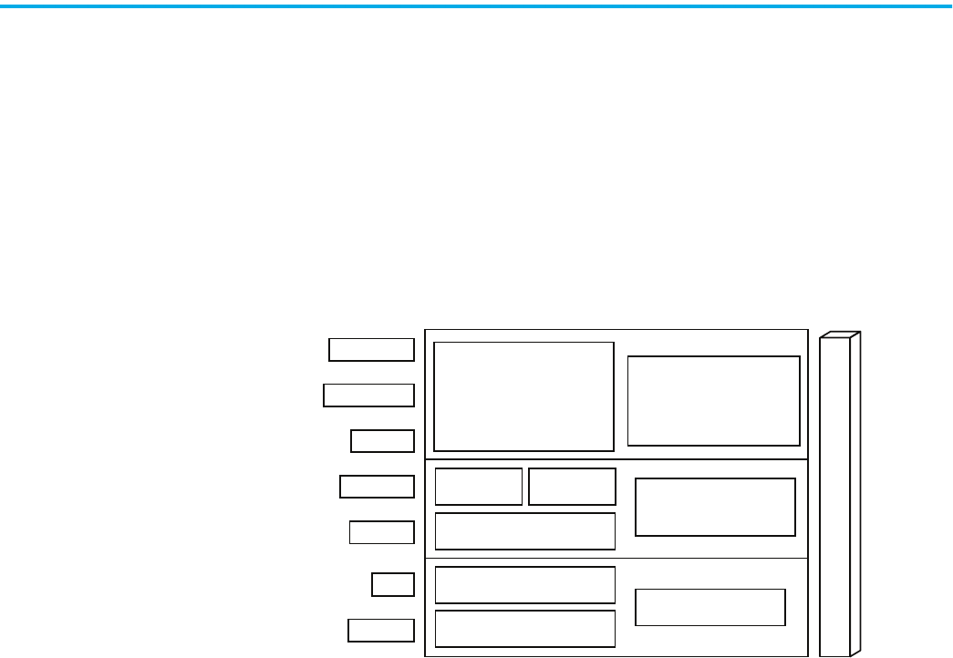
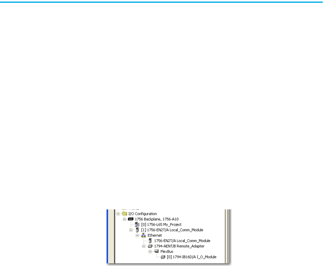
To build the I/O configuration for a typical I/O network, follow these steps.
1. Add the device.
2. Add the remote device for distributed I/O.
3. Add the I/O modules.
This graphic shows the I/O configuration of the consumer controller after
distributed I/O modules are added.
50 Rockwell Automation Publication ENET-UM006B-EN-P - May 2022
Chapter 5 Configure the Device
Configure EtherNet/IP
Communication
To configure the device, follow these steps.
1. Make sure that the device is installed, started, and connected to the
controller.
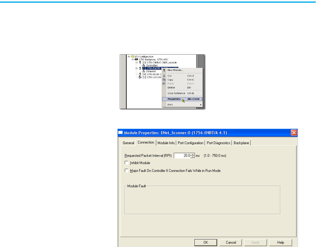
2. In the Controller Organizer, right-click the device and choose Properties.
The Module Properties dialog box appears.
3. Make configuration selections on the individual tabs.
4. Click OK.

Rockwell Automation Publication ENET-UM006B-EN-P - May 2022 51
Chapter 5 Configure the Device
Produced and Consumed
Data
Logix controllers can produce (broadcast) and consume (receive) system-
shared tags that are sent and received via the device. Produced and consumed
tags each require connections.
All EtherNet/IP™ devices support as many as 32 produced multicast
connections.
Each tag that passes through an EtherNet/IP device uses one connection. Due
to this feature, the number of available connections limits the total number of
tags that can be produced or consumed. If the device uses all of its connections
for I/O and other devices, no connections remain for produced and consumed
tags.
For more information, see Logix 5000 Controllers Produced and Consumed
Tags Programming Manual, publication 1756-PM011
.
Message Instructions Messages transfer data to other devices, such as other controllers or operator
interfaces. Each message uses one connection, regardless of how many devices
are in the message path. To conserve connections, you can configure one
message to read from or write to multiple devices.
For more information on programming MSG instruction, see the Logix 5000™
Controller General Instructions Reference Manual, publication 1756-RM003
.
Tag Type Required Connections
Produced
The local controller (producing) must have one connection for the produced tag
and the first consumer and one more connection for each additional consumer
(heartbeat). The produced tag requires two connections.
As you increase the number of controllers that can consume a produced tag, you
also reduce the number of connections the controller has available for other
operations. Example operations include communication and I/O.
Consumed
Each consumed tag requires one connection for the controller that is consuming
the tag.
IMPORTANT: When you configure a consumed tag, you must add a remote device
to the programming software project for the producing controller to configure the
consuming controller. The default Comm Format when adding a remote device to
the project is rack-optimized.
Change the Comm Format to None when adding the remote device.
IMPORTANT
Depending on whether it is producing or consuming a tag, a Logix
5000™ controller uses its connections differently.

52 Rockwell Automation Publication ENET-UM006B-EN-P - May 2022
Chapter 5 Configure the Device
Notes:
Rockwell Automation Publication ENET-UM006B-EN-P - May 2022 53
Chapter 6
Send Email
This chapter describes how to send an email through an EtherNet/IP™
communication module.
For email, the EtherNet/IP communication module can be remote or local to
the controller.
EtherNet/IP Communication
Module as an Email Client
The EtherNet/IP communication module is an email client that uses a mail
relay server to send email.
The EtherNet/IP communication module sends only the content of an MSG
instruction as an email to a mail relay server. Delivery of the email depends on
the mail relay server. The EtherNet/IP communication module does not
receive email.
IMPORTANT
The EtherNet/IP communication module can send an email to only
one recipient at a time. The module cannot mail to a distribution
list.
Table 7 - Ethernet Email
Desired Action Required Tasks
Send an email to specific personnel when a controller
application generates an alarm or reaches a certain
condition
Program the controller to send an MSG instruction to the
EtherNet/IP communication module
The MSG instruction then instructs the
EtherNet/IP communication module to send the email text
(contained within the MSG instruction) to the mail relay
server.
Multiple controllers can use the same EtherNet/IP
communication module to initiate email.
Send controller or application status information
regularly to a project manager
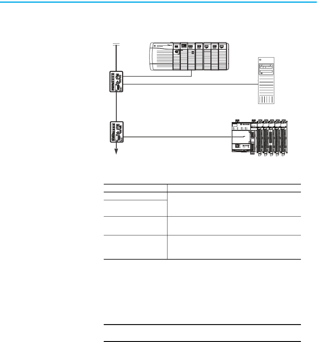
54 Rockwell Automation Publication ENET-UM006B-EN-P - May 2022
Chapter 6 Send Email
Figure 2 - Sample System
Send Email Via a Controller-
initiated Message
Instruction
A Logix controller can send a generic CIP™ message instruction to the
EtherNet/IP communication module that instructs the module to send an
email message to an SMTP mail relay server that uses the standard SMTP
protocol. This process automatically communicates controller data and
application conditions to appropriate personnel.
Some mail relay servers require a domain name be provided during the initial
handshake of the SMTP session. For these mail relay servers, specify a domain
name when configuring the network settings of the EtherNet/IP
communication module.
Logix5575
Redundancy Module
EtherNet/IP
PRI COM OK
ControlNet
EtherNet/IP
ControlNet
OKFORCE SDRUN
R
U
N
R
E
M
P
R
O
G
1 2
LNK1 LNK2 OK
10/100 BASE T
LNK NET OK
EtherNet/IP
LNK NET OK
Firewall/Router
ControlLogix® 5580 Controller With 1756-ENBT, 1756-EN2F, 1756-EN2T, 1756-
EN2TR, 1756-EN2TXT, 1756-EN3TR, or 1756-EN4TR Module
Ethernet Switch
Ethernet Switch
CompactLogix™ 5380 Controller
Mail Relay
Server
Table 8 - Sample System Capabilities
Device Capability
ControlLogix controller Send an MSG instruction to the 1756-ENBT module to initiate sending an
email to the mail relay server.
Use the path of the MSG instruction to identify the 1756-ENBT module as
the target of the MSG instruction.
CompactLogix controller
ControlLogix 5580 Controller
Send an email to the mail relay server from the email interface on the
Send an Email link.
This interface requires that you enter all email information.
Mail relay server
Send email to specified recipients.
The mail relay server determines the delivery of any email that is sent
through an EtherNet/IP communication module, whether via an MSG
instruction or from its built-in interface.
IMPORTANT
Be careful to write the ladder logic to be sure the MSG instructions
are not continuously triggered to send email messages.
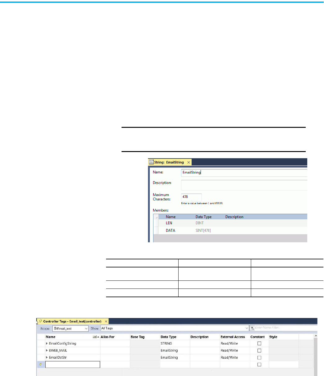
Rockwell Automation Publication ENET-UM006B-EN-P - May 2022 55
Chapter 6 Send Email
Create String Tags
You need three controller-scoped string tags. Each tag performs one of
these functions:
• Identifies the mail server
• Contains the email text
• Contains the status of the email transmission
The default STRING data type supports up to 82 characters. In most cases, this
limit is sufficient to contain the address of the mail server. For example, to
create tag EmailConfigstring of type STRING, follow these steps.
1. Create a String Type “EmailString” and enter 478 as the maximum
number of characters.
2. Open the tag editor and create the following tags.
IMPORTANT
An email message must not exceed 474 characters in length.
An additional 4-byte string-length value is added to the tag.
As a result, the maximum source length is 478 characters.
Tag Name Value Data Type
EmailConfigString
Enter the IP Address or Host Name of
Server
STRING
EmailDstStr 1 EmailString
EWEB_EMAIL Enter Email Addresses, see step .. EmailString
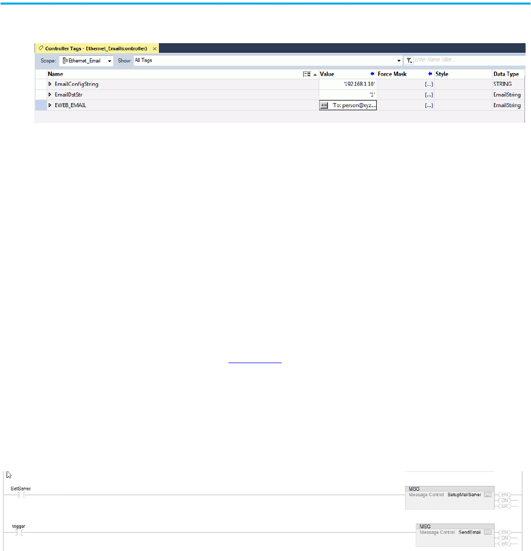
56 Rockwell Automation Publication ENET-UM006B-EN-P - May 2022
Chapter 6 Send Email
3. Enter email addresses in the Value column of the Controller Tags dialog
box
4. Type your email.
Use the string browser to type the text of the email. To include To:,
From:, and Subject: fields in the email, use <CR><LF> symbols to
separate each of these fields. The To: and From fields are required; the
Subject: field is optional. For example:
To: Email address of recipient <CR><LF>
From: Email address of sender <CR><LF>
Subject: subject of message <CR><LF>
body of email message
The text of the email does not have to be static. You can program a
controller project to collect specific data to be sent in an email.
For more information on how to use ladder logic to manipulate string data, see
the Logix 5000™ Controllers Common Procedures Programming Manual,
publication 1756-PM001
.
Enter the Ladder Logic
Ladder logic requires two MSG instructions. One MSG instruction configures
the mail server and must be executed only once. The second MSG instruction
triggers the email. Execute this email MSG instruction as often as needed.
The first rung configures the mail server. The second rung sends the email
text.
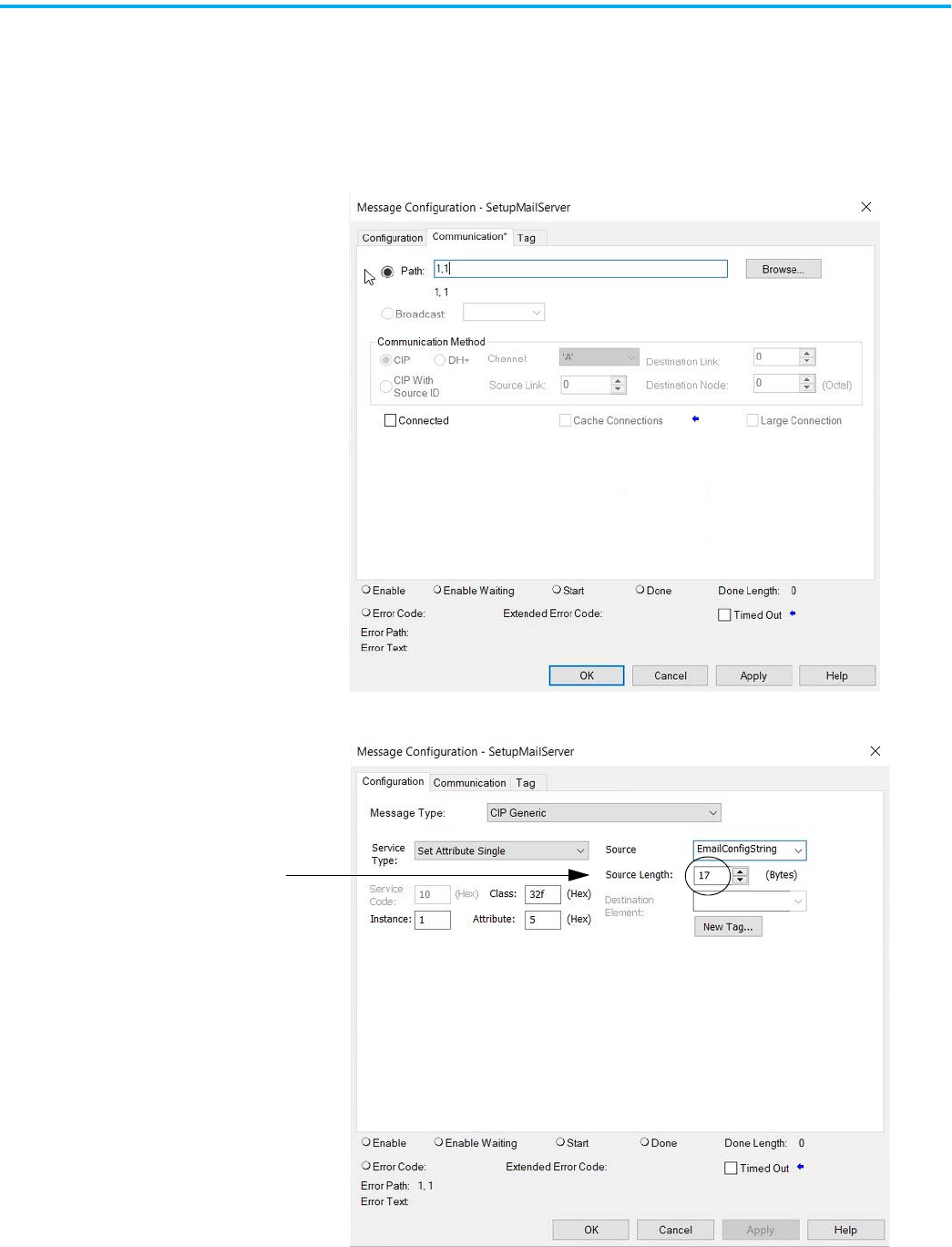
Rockwell Automation Publication ENET-UM006B-EN-P - May 2022 57
Chapter 6 Send Email
Configure the MSG Instruction That Identifies the Mail Relay Server
To configure the MSG instruction that identifies the mail relay server, follow
these steps.
1. On the communications tab, enter the communication path from the
controller to the email server.
2. On the configuration tab, enter the MSG parameters for the email server.
The Source Length is the number of characters in the STRING tag that
identifies the mail relay server plus 4 characters.
In this example, the tag contains 13 characters.
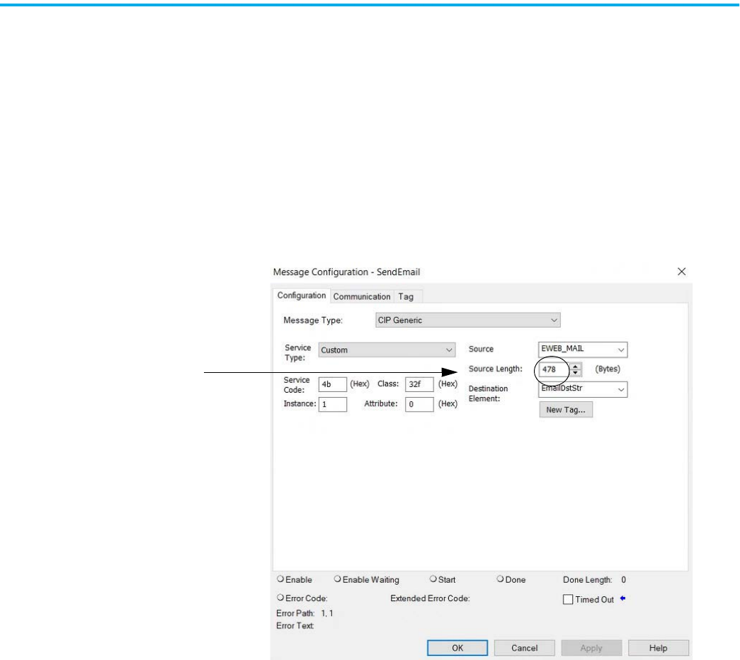
58 Rockwell Automation Publication ENET-UM006B-EN-P - May 2022
Chapter 6 Send Email
After the MSG instruction that configures the mail relay server
executes successfully, the controller stores the mail relay server
information in nonvolatile memory. The controller retains this
information, even through power cycles, until another MSG
instruction changes the information.
Configure the MSG Instruction That Contains the Email Text
To configure the MSG instruction that contains the email text, perform this
procedure.
1. On the configuration tab, enter the MSG parameters for the email.
The Source Length is the number of characters in the STRING tag that
contain the email plus 4 characters.
In this example, the email contains 474 characters.
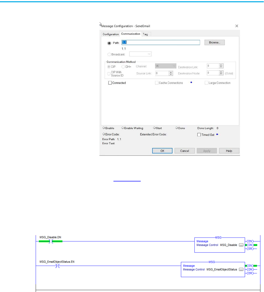
Rockwell Automation Publication ENET-UM006B-EN-P - May 2022 59
Chapter 6 Send Email
2. On the Communication tab, configure the path to the EtherNet/IP
device.
For more information on how to configure the path of an MSG instruction, see
the Logix 5000 Controllers General Instructions Reference Manual,
publication 1756-RM003
.
Configure the Email Object
Ladder logic requires two MSG instructions. One MSG instruction disables the
mail server and must be executed only once. The second MSG instruction
enables the email. Execute this email MSG instruction as often as needed.
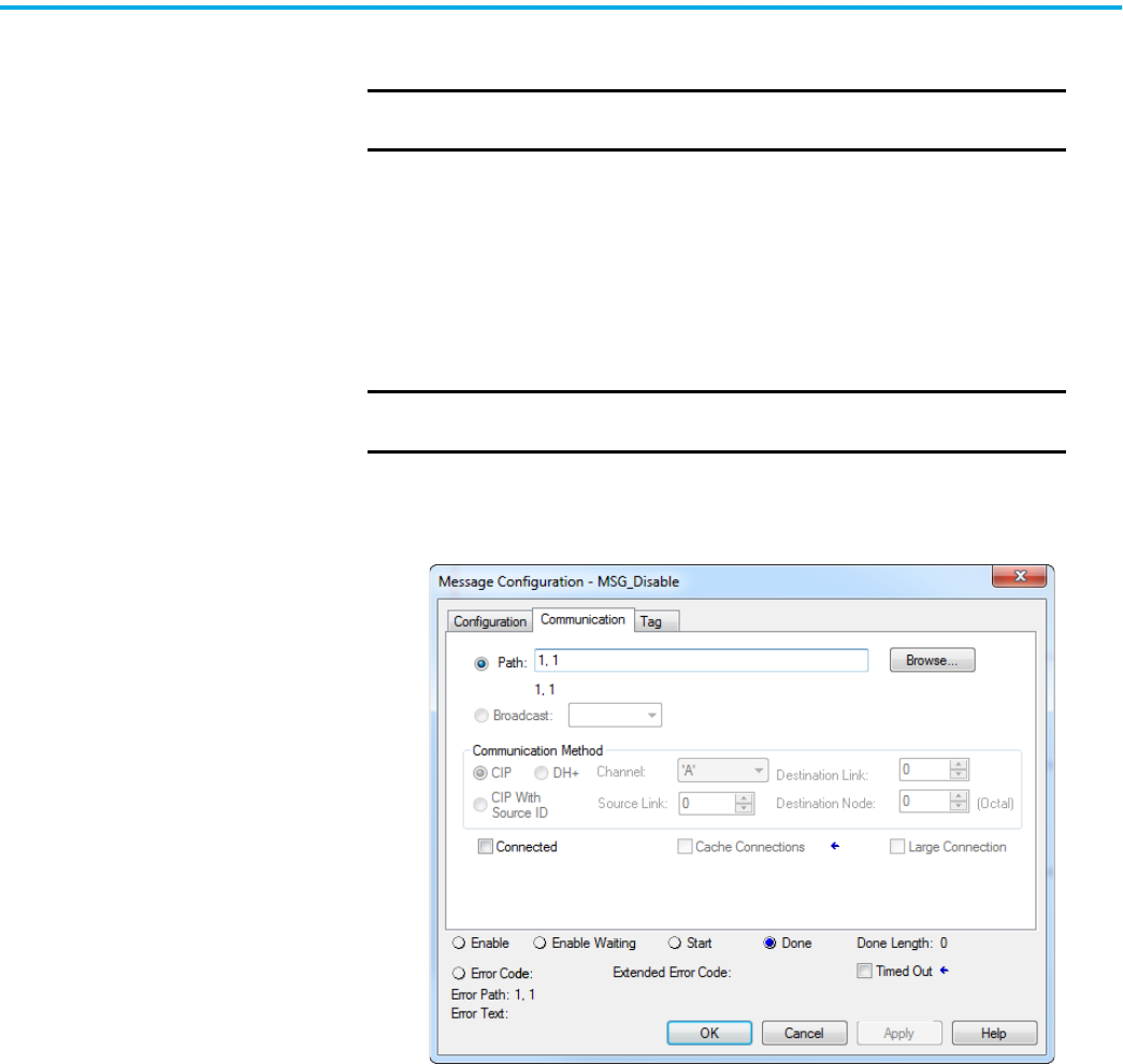
60 Rockwell Automation Publication ENET-UM006B-EN-P - May 2022
Chapter 6 Send Email
Disable the Email Object
You can disable the Email Object by setting the class attribute 0x08 to 0. After
that operation, all object-specific services and all instance attributes are
unavailable for writing and reading. Furthermore, the Object Enable attribute
is read-only. The Email Object is permanently disabled and a factory reset is
required to enable it again.
To disable the Email Object, perform this procedure.
1. Create a tag DisableEmailObject of type SINT.
2. Create a MSG instruction that uses tag MSG_Disable.
3. On the Communication tab, enter the path.
IMPORTANT
If you disable the Email Object, it is permanently disabled and a
factory reset is required to enable it again.
IMPORTANT
1756 EtherNet/IP communication modules with firmware 10.010 or
higher support this feature.
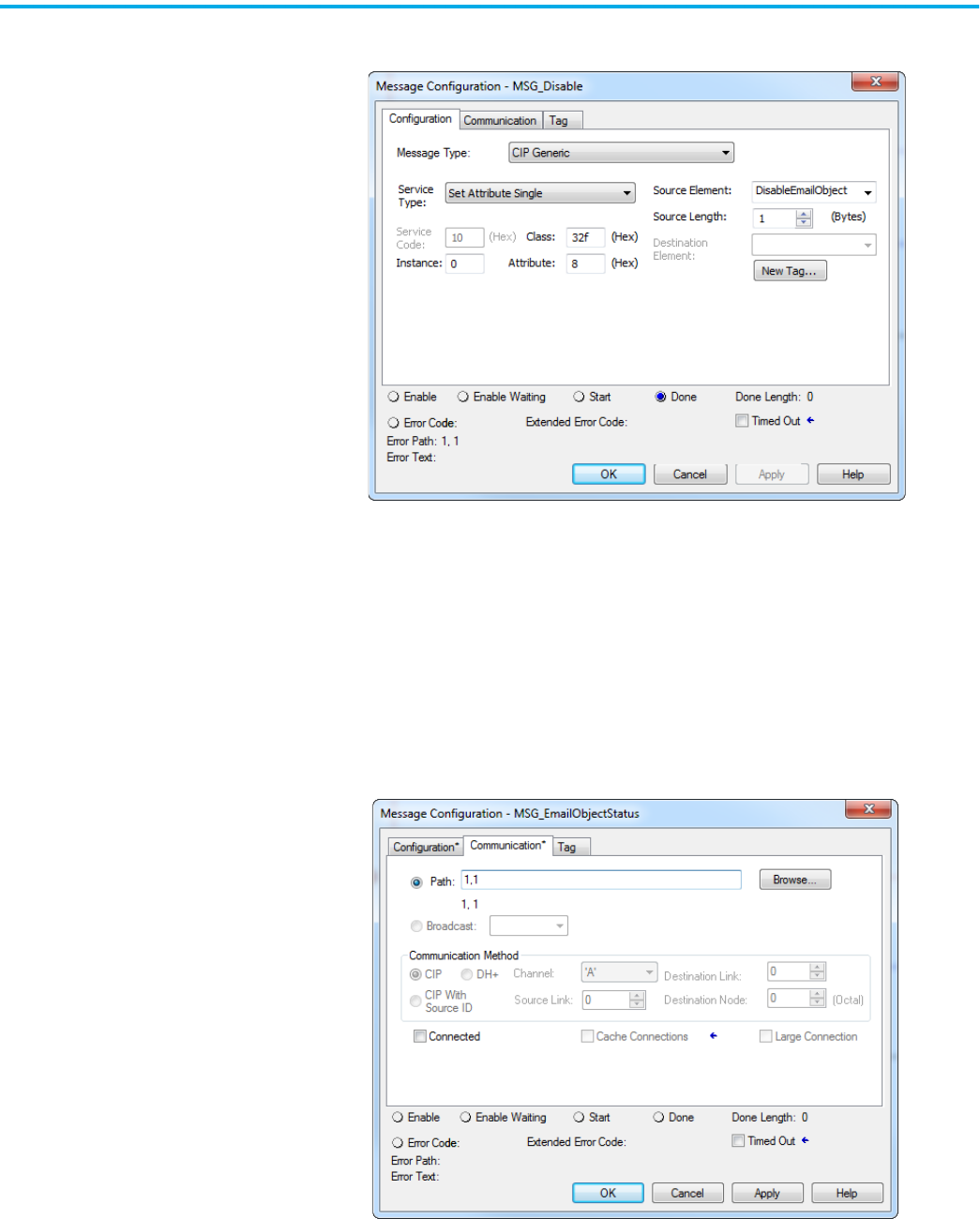
Rockwell Automation Publication ENET-UM006B-EN-P - May 2022 61
Chapter 6 Send Email
4. On the Configuration tab, enter these parameters.
When this MSG instruction executes, the value is returned in the second
message. Since there is no destination element, you do not get a response.
However, you receive the DN bit set.
Get Email Object Status
To determine if the email object is disabled, perform this procedure.
1. Create a tag EmailObjectStatus of type SINT.
2. Create a MSG instruction that uses tag MSG_EmailObjectStatus.
3. On the Communication tab, enter the path.
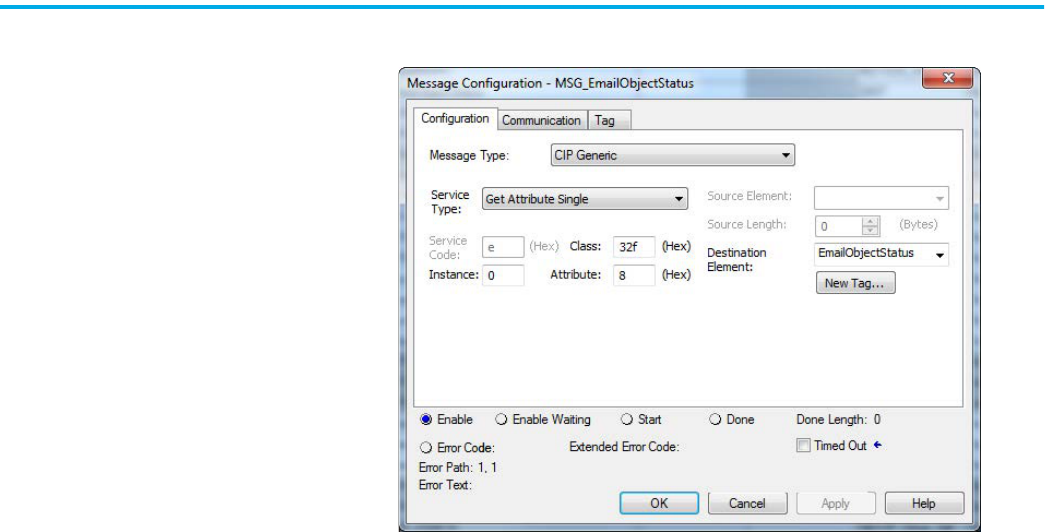
62 Rockwell Automation Publication ENET-UM006B-EN-P - May 2022
Chapter 6 Send Email
4. On the Configuration tab, enter the following parameters.
When the MSG instruction executes:
• If the MSG_EmailObjectStatus.DN bit is set and the value of the
EnableObjectStatus is 0, then the Email Object is disabled.
• If the value of the EnableObjectStatus is 1, then the Email Object is
enabled.
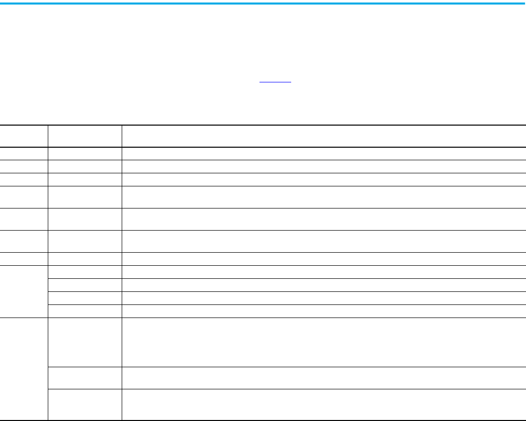
Rockwell Automation Publication ENET-UM006B-EN-P - May 2022 63
Chapter 6 Send Email
Possible Email Status Codes Examine the destination element of the email MSG to see whether the email
was successfully delivered to the mail relay server. A successful delivery
indicates that the mail relay server placed the email message in a queue for
delivery. This notification does not mean that the intended recipient received
the email message. Table 9
lists the possible codes that a destination element
could contain.
Table 9 - Email Status Code Descriptions
Error Code
(Hex)
Extended-error Code
(Hex)
Description
0x00 None Delivery successful to the mail relay server.
0x02 None Resource unavailable. The email object was unable to obtain memory resources to initiate the SMTP session.
0x08 None Unsupported Service Request. Make sure that the Service Code is 0x4B and the Class is 0x32F.
0x11 None
Reply data too large. The Destination string must reserve space for the SMTP server reply message. The maximum reply can be 470
bytes.
0x13 None
Configuration data size too short. The Source Length is less than the Source Element string size plus the 4-byte length. The Source Length
must equal the Source Element string size + 4.
0x15 None
Configuration data size too large. The Source Length is greater than the Source Element string size plus the 4-byte length. The Source
Length must equal the Source Element string size + 4.
0x19 None Data write failure. An error has occurred when attempting to write the SMTP server address (attribute 4) to nonvolatile memory.
0xFF
0x0100 Error that an email server returns; check the Destination string for reason. The email message was not queued for delivery.
0x0101 SMTP mail server not configured. Attribute 5 was not set with an SMTP server address.
0x0102 ‘To:’ address not specified. Attribute 1 was not set with a ‘To:’ address AND there is not a ‘To:’ field header in the email body.
0x0103 ‘From:’ address not specified. Attribute 2 was not set with a ‘From:’ address AND there is not a ‘From:’ field header in the email body.
0xFF
0x0104
Unable to connect to SMTP mail server set in Attribute 5. If the mail server address is a host name, make sure that the device supports
DNS, and that a Name Server is configured. If the host name is not fully qualified, for example, ‘mail host’ and not ‘mailhost.xx.yy.com’
then the domain must be configured as ‘xx.yy.com’. Try ‘ping <mail server address>’ to make sure that the mail server is reachable from
your network. Also try ‘telnet <mail server address> 25’, which attempts to initiate an SMTP session with the mail server via telnet over
port 25. (If you connect then type ‘QUIT’).
0
x
0105
Communication error with SMTP mail server. An error occurred after the initial connection with the SMTP mail server.
See the ASCII text following the error code for more details as to the type of error.
0x0106
SMTP mail server host name DNS query did not complete. A previous send service request with a host name as the SMTP mail server
address did not yet complete. A timeout for a DNS lookup with an invalid host name can take up to 3 minutes. Long timeouts can also
occur if a domain name or name server is not configured correctly.

64 Rockwell Automation Publication ENET-UM006B-EN-P - May 2022
Chapter 6 Send Email
Notes:

Rockwell Automation Publication ENET-UM006B-EN-P - May 2022 65
Index
B
BOOTP/DHCP
disable with RSLinx Classic software
46
BOOTP/DHCP tool
set network IP address
44 - 45
C
capacity
packet rate
13
CIP
connections
11
types
12
client and server
10
configure
communication drivers
30 - ??
EtherNet/IP communication driver 30 - 31
MSG instructions
58
set network IP address
?? - 40, 44 - ??
with RSLinx Classic software 41 - 43
workstation
30 - ??
connections 8
CIP
11
direct 11
rack-optimized
11
TCP
10
consumer 10
D
DHCP server 48
direct connections
11
DNS addressing
19
duplicate address detection
18
E
email
MSG instruction
58
overview
53
send through an EtherNet/IP module 53 - 63
sending via MSG instruction
54 - 59
status codes
63
Ethernet communication driver 30 - 31
EtherNet/IP communication driver
30 - 31
EtherNet/IP network
module features
22
overview
7
explicit
connections
11
messages 14
I
implicit
connections
11
messages 13
IP address
duplicate address detection
18
set with RSLinx Classic software
41 - 42
M
messages
explicit
14
implicit
13
types 11
MSG instruction
sending email
58
sending via an email
54 - 59
N
network parameters
DNS addressing
19
O
overview
EtherNet/IP network
7
P
packets
rate capacity
13
R
rack-optimized connections 11
RSLinx Classic software
configure network parameters
41 - 43
disable BOOTP/DHCP
46
Ethernet communication driver
30 - 31
set IP address 41 - 42
S
set IP address
with RSLinx Classic software
41 - 43
set network IP address
BOOTP/DHCP tool
44 - 45
software
RSLinx Classic
configure network parameters
41 - 43
status codes
email
63
string tags
55


Rockwell Automation Publication ENET-UM006B-EN-P - May 2022 67
EtherNet/IP Network Devices User Manual

Publication ENET-UM006B-EN-P - May 2022
Supersedes Publication ENET-UM006A-EN-P - November 2019 Copyright © 2022 Rockwell Automation, Inc. All rights reserved. Printed in the U.S.A.
Rockwell Automation Support
Use these resources to access support information.
Documentation Feedback
Your comments help us serve your documentation needs better. If you have any suggestions on how to improve our
content, complete the form at rok.auto/docfeedback
.
Waste Electrical and Electronic Equipment (WEEE)
Rockwell Automation maintains current product environmental information on its website at rok.auto/pec.
Technical Support Center Find help with how-to videos, FAQs, chat, user forums, and product notification updates. rok.auto/support
Knowledgebase Access Knowledgebase articles. rok.auto/knowledgebase
Local Technical Support Phone Numbers Locate the telephone number for your country. rok.auto/phonesupport
Literature Library Find installation instructions, manuals, brochures, and technical data publications. rok.auto/literature
Product Compatibility and Download Center
(PCDC)
Download firmware, associated files (such as AOP, EDS, and DTM), and access product release
notes.
rok.auto/pcdc
At the end of life, this equipment should be collected separately from any unsorted municipal waste.
Rockwell Otomasyon Ticaret A.Ş. Kar Plaza İş Merkezi E Blok Kat:6 34752, İçerenkÖy, İstanbul, Tel: +90 (216) 5698400 EEE YÖnetmeliğine Uygundur
Allen-Bradley, CompactLogix, ControlLogix, expanding human possibility, FactoryTalk, Flex 5000, Flex I/O, Kinetix, Logix 5000, PanelView, PowerFlex, Rockwell Automation, Rockwell Software, RSLinx,
Studio 5000, and Studio 5000 Logix Designer are trademarks of Rockwell Automation, Inc.
CIP, CIP Motion, CIP Safety, CIP Security, and EtherNet/IP are trademarks of ODVA, Inc.
Trademarks not belonging to Rockwell Automation are property of their respective companies.
